Mechanical Endstop
Contents
Overview
How to wire a mechanical switch to replace an optical endstop.
Good reasons
- The flags wont bend.
- Cheaper.
- No need for opto pcb.
- Simple switches can be used on x and y axis.
- You could even make your own contact switch from a few pieces of metal.
- A simple way to put in max endstops.
- You get to solder stuff.
Bad reasons
- Switches have a limited amount of on/off cycles. (Especially cheap ones).
- Needs new way to mount switch, which will depend on the switch type.
- The resolution and repeated function of the triggered distance is very critical on the z axis.
- You have to solder stuff.
Opto Endstop v1.0, v2.1 and Tech Zone Remix
How to replace Opto Endstop v1.0, Opto Endstop v2.1 and Tech Zone Remix Endstop which share the same basic design.
Interface
Copied from DarwinOptoEndstop#Interface
| Pin | Function |
| +5 | This is the pin to supply +5 volts on. |
| S | This is the signal pin. It will output high (+5) if it is triggered, or low (0v) if it is clear |
| G | This is the ground pin. |
Switch requirements
Single pole double throw (SPDT) switch, or an equivalent. Meaning you need a switch which connects two poles when not triggered. Read more at wikipedia.
For the z axis, high resolution (aka short trigger distance) and high repeatability is needed.
The x and y axis resolution is not that important, unless you home the machine during a print. But you are of course encouraged to use a high quality switch if you can, as it certainly won't hurt.
Where to buy switches
Ebay ...
Switch wiring
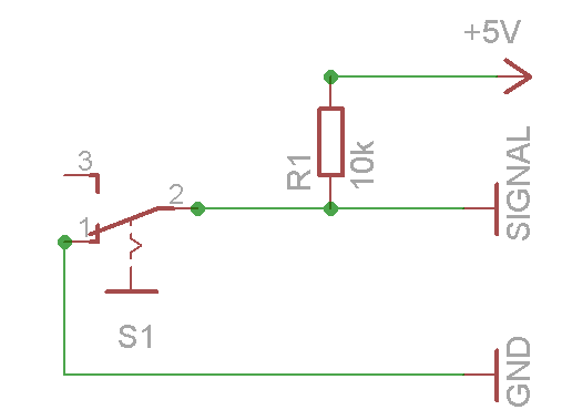
When the switch is off (like in the schematic above), it connects signal to ground. When the switch is triggered, the ground connection is cut and the signal is connected to 5v through the pull up resistor.
Make sure you keep the wires away from the motor leads and / or used screened cable as it is easy to pick up enough noise to get false triggering. [1]
Optional LED
If you want an indicator, you can hook up a LED (and a matching resistor).
...
Generation 6 endstops
...
Switch mounting
You need a way to mount the switch on the printer. Feel free to share your solutions and designs here. Modular design encouraged to fit different switches.
Mendel
X axis
A bracket between the smooth rods on the gantry, with the switch triggered by the x carriage body.
Y axis
...
Z axis
Mounted on the z smooth rod, with the switch triggered by the x gantry. Needs to sit very securely, but still be easy adjustable in small increments.
