MiniRambo
Release status: Working
| Description | Smaller version of RAMBo with 4 stepper drivers.
|
| License | Creative Commons Attribution-ShareAlike 3.0
|
| Author | |
| Contributors | |
| Based-on | |
| Categories | |
| CAD Models | |
| External Link |
RAMBo Pages: RAMBo .:. RAMBo v1.0-1.1 .:. RAMBo v1.2 .:. RAMBo v1.3 .:. RAMBo v1.4 .:. RAMBo Firmware .:. RAMBo Development .:. MiniRambo .:. MiniRambo Development .:. EinsyRambo .:. EinsyRambo Development
Contents
Summary
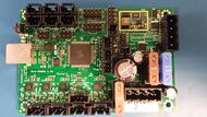
This board is based off RAMBo, the Arduino MEGA design, and the work of RepRap community. It has 4 stepper drivers and 4 mosfet switched outputs.
Version differences concerning LCD controllers
- 1.2+
- These versions have two 2x5 pin extension headers that are compatible with the RepRapDiscount LCD controllers.
- 1.0-1.1
- These earlier versions use finer pitch GPIO ports that were left off the board during manufacturing. Consequently, it would be difficult to add an LCD panel to these boards.
Differences from Rambo
MiniRambo has:
- 4 stepper drivers vs. 5
- 3 Thermistor jacks vs. 4
- 4 total mosfets vs. 6
- PWM control of stepper current vs. Digital Trimpot
- Can connect RepRapDiscount LCD cables directly without an adapter board. (version 1.3a only)
- Less general purpose IO connectors than Rambo.
Powering Mini-Rambo
MiniRambo you must connect power to the Primary Power input for RAMBo to operate. The USB connection is isolated from the rest of the board and cannot be a power source.
Features
Logic
- Arduino MEGA compatible Atmega2560 and Atmega32u2 processors are compatible with all RAMPS class firmware
- Crystals for both usb and mcu (timing accurate to 10ppm)
- 3 Thermistor jacks
Motor Drivers
- 4 A4982 1/16th microstep motor drivers(2 connectors on Z for Prusa Mendel and other dual Z printer designs)
- PWM Outputs for (XY), Z, E0 stepper current control instead of digital trimpot.
- Current limit on driver IC VCC to prevent permanent latchup
- Microstep mode configured by MCU through firmware (no jumpers needed)
- Test points for driver control signals
- Step and Direction pins are on their own ports for synchronous movement capability
PWM DC outputs (Extruders, Fans, Etc.)
- 4 outputs (1 Extruder, 1 BED, 2 low power (fan,etc)
- Low resistance mosfets for cool running
- Indicator led for each channel
Power
- 2 power input rails
- Heated Bed, 15A 12-35V
- Primary Power 10A 12-28V: Motors (5A dedicated fuse) + Extruders, Fans, & Logic (5A dedicated fuse)
- Built in SMPS for 5V generation from Extruders + fans and logic
PCB
- 4 layer
- 2oz copper on all layers
- High quality, High temperature FR4-TG130 PCB
- Gold ENIG finishing
Connectors
- 4-pin motor plug - Molex 5057-9404
- 3-pin end-stop plug - Molex 5057-9403
- 2-pin thermistor plug - Molex 5057-9402
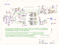
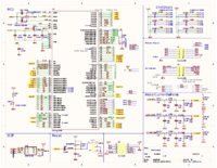
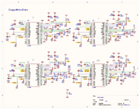
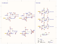
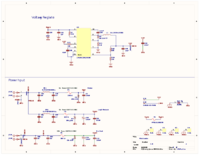
Schematic
Fuses
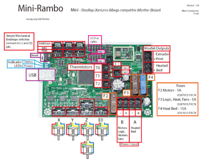
MiniRambo has 3 user replaceable ATO fuses (the type found in many automotives).
- F1 5A supplies the motors.
- F2 5A supplies the extruder heater + fan outputs and logic.
- F3 15A supplies the heated bed output.
Firmware
Firmware Requirements
MiniRambo just like Rambo needs ArduinoAddons to be installed to make use of all the pins. Not installing ArduinoAddons can result in only partially working features. ArduinoAddons can be installed manually or by the new board manager third party url feature. Rambo_firmware#Arduino_1.6.4.2B_Board_Manager_Plugin
Manual Installation Example:
Copy this folder from marlin "MarlinDev-master\ArduinoAddons\Arduino_1.6.x\hardware\marlin" to arduino's hardware directory "arduino-1.6.4\hardware"
Marlin 1.1 RC(RC branch)
https://github.com/MarlinFirmware/Marlin/tree/RC/Marlin
This firmware requires a change in Configuration.h:
#define MOTHERBOARD BOARD_MINIRAMBO
Marlin 1.0.2 (old fork)
fork with Thermal Runaway Protection during heatup phase
https://github.com/tonokip/Marlin/tree/1.0.2-TRP
This firmware requires a change in Configuration.h:
#define MOTHERBOARD 302
Marlin development tree
https://github.com/MarlinFirmware/MarlinDev/
Warning: this firmware is probably broken due to major development.
This firmware requires a change in Configuration.h:
#define MOTHERBOARD BOARD_MINIRAMBO
REPRAP_DISCOUNT_FULL_GRAPHIC_SMART_CONTROLLER
Using this Graphical LCD controller requires a fix in Marlin source code. In the file "ultralcd_st7920_u8glib_rrd.h" change this line:
#pragma GCC optimize (3)
To:
#pragma GCC optimize (0)
- Note: This fix is only for the Graphical LCD. The bug is caused by the firmware sending the data too fast over the software implementation of SPI.
- Repo with modification: https://github.com/tonokip/Marlin/tree/1.0.2-TRP-MiniRamboGLCD
Changing Motor Current (similar to Trimpot/Digipot)
In pins_MINIRAMBO.h (newer firmware) or pins.h (older firmware) you can change this line:
#define DEFAULT_PWM_MOTOR_CURRENT {1300, 1300, 1250} // XY Z E0
The motor current is controlled by a PWM signal that is turned into a voltage using an RC circuit. It is then fed to the stepper drivers Vref pin. A good troubleshooting tip is to check the Vref test points with a multimeter. The test points are labeled on the PCB as XREF, ZREF, and EREF and are found in the vicinity between the double Z motor connectors and the CPU.
The motor currents can be set during run time using the mcode M907 in Marlin. Recommended for testing purposes only.
M907 X100 Z100 E100 ;Max 255
PWM Pin for a Servo (pin remapping)
There are no "extra" PWM capable pins on MiniRambo for a servo. The Min Endstop pins are PWM capable. If you use min endstops then one of them can be freed up by remapping it to the Max pin.
In "pins.h" under the Mini-Rambo section or "pins_MINIRAMBO.h" (on newer firmware) you will find the pin mapping that need to be modified.
To move X-min to X-max modify the following lines:
#define X_MIN_PIN 12
#define X_MAX_PIN 24
To this:
#define X_MIN_PIN 24 //12
#define X_MAX_PIN -1 //24
This will free up digital pin 12 (X-min signal pin) as the PWM capable pin for a servo. This same concept works for Y and Z endstops.
Example modification here: https://github.com/tonokip/Marlin/commit/f53b6f272d524b99b3c99282c8671416c7dc10db
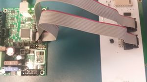
RepRapDiscount LCD Cables Connection Example
USB Driver
Mini-Rambo uses the same Windows CDC driver as the RAMBo USB driver.
Changelog
- 1.3
- change fuse holder
- change fan Mosfet
- silkscreen fixes
- layout improvements
- 1.2
- extension headers changed to 2.54mm pitch
- fix schematic typos
- 1.1
- change soft start capacitor value
- add filter capacitors to motor outputs
Troubleshooting
This is a generic troubleshooting guide. These steps may vary depending on manufacturer configuration. Contact your supplier if these steps do not help.
- Cannot connect with 3D printing control software
- Is the power indicator LED on?
- Make sure the power is connected as described in :Powering Mini-Rambo.
- Is a fuse blown? MiniRambo fuses
- Is correct driver installed? RAMBo USB driver
- Is there firmware installed on your Mini-Rambo? Mini-Rambo firmware
- Is the power indicator LED on?
- All Heater and Fan LEDs stay lit when board is powered.
- Check that the power source is not plugged into the Heater outputs.
