Rambo v1.2
RAMBo Pages: RAMBo .:. RAMBo v1.0-1.1 .:. RAMBo v1.2 .:. RAMBo v1.3 .:. RAMBo v1.4 .:. RAMBo Firmware .:. RAMBo Development .:. MiniRambo .:. MiniRambo Development .:. EinsyRambo .:. EinsyRambo Development
This page is applicable for RAMBo version 1.2
See RAMBo for general RAMBo details including firmware, configuration, drivers, etc. See RAMBo v1.1 for information applicable to version 1.0 through 1.1.
Contents
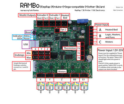
Powering RAMBo 1.2
Starting v1.2 you must connect power to the Heater, Fans, and Logic input for the RAMBo to operate. The USB connection is now isolated from the rest of the board and cannot be a power source.

Features
Logic
- Arduino MEGA compatible Atmega2560 and Atmega32u2 processors are compatible with all RAMPS class firmware
- Crystals for both usb and mcu (timing accurate to 10ppm)
- 4 Thermistor jacks
- All extra pins broken out on both processors (allows using the 32u2 for LUFA AVR programmer, etc.)
Motor Drivers
- 5 A4982 1/16th microstep motor drivers(2 connectors on Z for Prusa Mendel and other dual Z printer designs)
- Digital Trimpot for stepper current control
- Current limit on driver IC VCC to prevent permanent latchup
- Microstep mode configured by MCU through firmware (no jumpers needed)
- Test points for driver control signals
- Step and Direction pins are on their own ports for synchronous movement capability
- Extra driver ports broke out for up to 3 additional drivers (some of the motor extension pins are shared with max endstop and a pin allocated for SPI-SS extensions)
PWM DC outputs (Extruders, Fans, Etc.)
- 6 outputs
- Low resistance mosfets for cool running
- Indicator led for each channel
Power
- Three independent power rails for flexible input power configurations
- Heated Bed, 15A 12-35V
- Extruders + fans and logic, 5A 12-35V (fuse can be exchanged for up to 10A capacity)
- Motors, 5A 12-35V (fuse can be exchanged for up to 10A capacity)
- Built in SMPS for 5V generation from Extruders + fans and logic
PCB
- 4 layer
- 2oz copper on all layers
- High quality, High temperature FR4-TG130 PCB
- Gold ENIG finishing
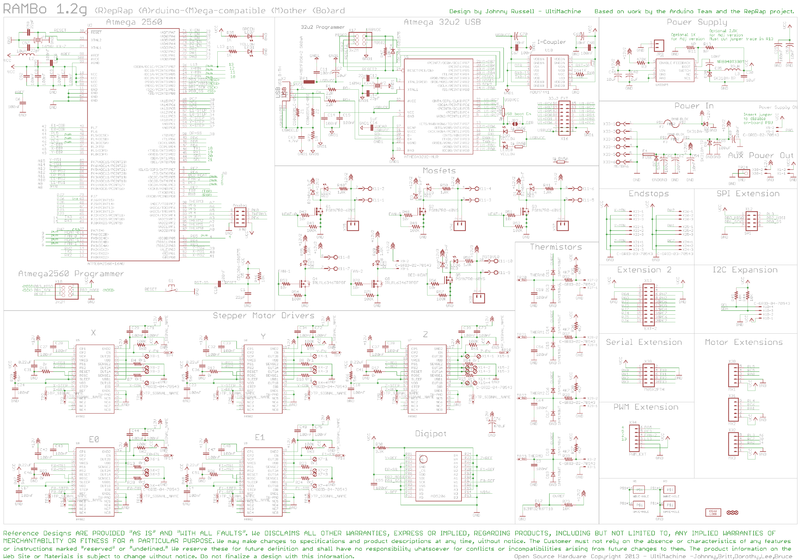
Schematic
Fuses
RAMBo v1.2 has 3 user replaceable fuses. The small white fuse holders are Little Fuse OMNI-BLOCK fuse holders. They are compatible with NANO2 Fuses. Fast or very fast acting are recommended. An example part number for replacement fuses is 0448005.MR
- F2 supplies the motors and on-board power supply.
- F3 supplies the extruder heater + fan outputs and logic.
- F4 is a 15A ATO (the type found in many automotives). F4 supplies the heated bed output.
USB static sensitivity
One of the goals of the v1.2 design was to separate the USB system from the rest of the board, improving the noise resistance. Unfortunately, this meant that static discharges into the USB port could fry the components between the two sections, disabling the USB port. Ultimachine has created a retrofit mod that plugs into two unused connectors on the board and provides for discharging the harmful voltages. Some boards have also been released with SMC modes to fix this, and version 1.2fp of the board includes the fix on the board.
According to an email by Brett of UltiMachine on 3/14/2014, if a specific board has been patched for this problem then its serial number sticker, located on the edge of the board between the endstop connectors and motor connectors, will have a suffix of "P".
Troubleshooting
This is a generic troubleshooting guide for RAMBo. These steps may vary depending on manufacturer configuration. Contact your supplier if these steps do not help.
- Cannot connect with 3D printing control software
- Is the power indicator LED on?
- Make sure the power is connected as described in :Powering RAMBo 1.2.
- Is F3 blown? Rambo fuses
- Is correct driver installed? RAMBo USB driver
- Is there firmware installed on your RAMBo? Rambo firmware
- Is the power indicator LED on?

