RAMPS 1.4/fr
|
English • العربية • български • català • čeština • Deutsch • Ελληνικά • español • فارسی • français • hrvatski • magyar • italiano • română • 日本語 • 한국어 • lietuvių • Nederlands • norsk • polski • português • русский • Türkçe • українська • 中文(中国大陆) • 中文(台灣) • עברית • azərbaycanca • |
Release status: Working

| Description | RepRap Arduino Mega Pololu Shield
Arduino MEGA based modular RepRap electronics.
|
| License | |
| Author | |
| Contributors | |
| Based-on | |
| Categories | |
| CAD Models | |
| External Link |
Contents
- 1 Introduction
- 2 Règles de SÉCURITÉ
- 3 Assemblage
- 3.1 Component Soldering
- 3.2 Outils nécessaires
- 3.2.1 Assemblage de la carte
- 3.2.1.1 Condensateur C2 - 100nF
- 3.2.1.2 DIODE1 - LED Verte
- 3.2.1.3 LED2, LED3, LED4 - Red LED
- 3.2.1.4 Résistances R13, R14, R15 - 10 Ohm
- 3.2.1.5 Résistance R12 - 1K resistor
- 3.2.1.6 Résistances R23, R24, R25 - 1.8K
- 3.2.1.7 Résistances R1, R7, R11, R21, R22 - 4.7K
- 3.2.1.8 Résistances R16, R17, R18, R19, R20 - 10K
- 3.2.1.9 Résistances R2, R3, R4, R5, R6, R8, R9, R10 - 100K
- 3.2.1.10 Condensateurs C1, C5, C8 - 10uF
- 3.2.1.11 Condensateurs C3, C4, C6, C7, C9, C10 - 100uF
- 3.2.1.12 Reflow SMT soldering
- 3.2.1.13 Top pins
- 3.2.1.14 Driver sockets
- 3.2.1.15 D1, D2 - Diodes
- 3.2.1.16 F1 - MFR500 Fuse
- 3.2.1.17 Bottom pins
- 3.2.1.18 Le bouton RESET
- 3.2.1.19 Connecteurs aux Mosfets
- 3.2.1.20 Connecteur d'alimentation
- 3.2.1.21 Q1, Q2, Q3 - Mosfets
- 3.2.1.22 F2 - MFR1100 Fusible
- 3.2.1.23 Inspection
- 3.2.2 Cartes des pilotes des moteurs pas à pas
- 3.2.3 Fins de course optiques
- 3.2.4 Mechanical Endstops
- 3.2.5 Put the connectors on the motor wires
- 3.2.6 Thermistor Wires
- 3.2.7 Pololu carriage
- 3.2.1 Assemblage de la carte
- 4 Finalisation des réglages
- 5 Firmware and Pin Assignments
- 6 BT Extension
Introduction
Pour la RAMPS 1.4, les résistances et les condensateurs sont montés en surface (CMS ou SMD en anglais) afin de pouvoir contenir plus de composants passifs. Ceci rajoute des étapes d'assemblage supplémentaires, mais le fait que cette carte conserve des dimensions assez grandes rend la tâche beaucoup moins ardue.


Règles de SÉCURITÉ
Dès que vous brancherez votre RepRap (même avec du "simple" 12 Volts), vous devez impérativement respecter les règles basiques et élémentaires de prudence lorsque l'on travaille avec de l'électricité afin d'éviter les incendies. Comme personne n'est à l'abri d'un accident, n'hésitez pas à équiper votre atelier d'au moins un détecteur de fumée !!!
Assemblage
Component Soldering
Outils nécessaires
Vous devez avoir: un fer à souder, du fil de soudure, de bonnes pinces pour maintenir les composants Mais aussi : Une pompe à dessouder, de la tresse à dessouder, du flux pour souder Autre méthode possible : Pâte à souder, four ou plaque de cuisson
Assemblage de la carte

Souder la RAMPS 1.4 demande à la fois de souder des composants en surface et à travers des trous.
Le montage en surface peut se faire de différentes façons. Since all the SMT components on this board are large 2 pad parts you can do pin by pin soldering pretty easy with normal soldering equipment. Start by putting a small amount of solder on one pad. If you have flux, coat the soldered pad. Use the tweezers to hold the component down in position and heat the solder to tack the component into place (make sure the entire solder blob flows so you don't get a cold solder). Then solder the other pad. Also popular is using solder paste for pad by pad soldering, Oven Reflow (need link), and HotplateReflowTechnique
Commencez par souder les composants de surface. Ensuite les PTH en haut de la carte. Enfin terminez par les broches (pins) du bas.
Condensateur C2 - 100nF

Son orientation n'a pas d'importance.
DIODE1 - LED Verte

Place these with the end having green dots away from the + mark on the PCB.
LED2, LED3, LED4 - Red LED

Place these with the end having green dots away from the + mark on the PCB.
Résistances R13, R14, R15 - 10 Ohm

Leur orientation n'a pas d'importance.
Résistance R12 - 1K resistor

Son orientation n'a pas d'importance.
Résistances R23, R24, R25 - 1.8K

These are marked 1K on the PCB, but we are using larger ones to accommodate higher voltages. Leur orientation n'a pas d'importance.
Résistances R1, R7, R11, R21, R22 - 4.7K

Leur orientation n'a pas d'importance.
Résistances R16, R17, R18, R19, R20 - 10K

Leur orientation n'a pas d'importance.
Résistances R2, R3, R4, R5, R6, R8, R9, R10 - 100K

Leur orientation n'a pas d'importance.
Condensateurs C1, C5, C8 - 10uF

Veillez à bien respecter leur polarité. The board has the foot print of the components printed on it. The rounded corners on the base of the capacitor must line up with the white print on the PCB.
Condensateurs C3, C4, C6, C7, C9, C10 - 100uF

Veillez à bien respecter leur polarité. The board has the foot print of the components printed on it. The rounded corners on the base of the capacitor must line up with the white print on the PCB.
Reflow SMT soldering


If you are doing oven or hot plate method, now is the time apply heat (add links here). If you used a solder iron, you have probably already soldered all these components.
Make sure to inspect the SMT soldering at this point since it will be harder to rework after the headers are on top.
Top pins

Solder 1 1x6, 6 1x4, and 7 2x3 pin headers on top of the board. The long post should be standing up to take a connector. Solder one leg on each one to tack them into place. Then re-heat the joint and push on the component until it is perfectly situated. Then you'll want to solder the rest of the leads. You will get burnt if you touch the other side of the pin you are soldering.
If you want to use the extra pin outputs, now is the time to solder on the rest of the headers.
Driver sockets

Place the female headers for the stepper drivers on top of the board. You can use the 1x8 and 1x6 pin headers to jig them straight. Turn the board over and solder these pins.
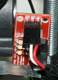
D1, D2 - Diodes


Respectez bien leur orientation. La bande tracée sur la diode doit être du même côté que la marque sur la carte.
Soudez D2 à son emplacement. On voit D2, F1, et F2 installés sur l'image ci-contre.
D1 ne doit être installée que si l'arrivée 5A est alimenté avec du 12V. Elle peut être omise et dans ce cas l'Arduino sera alimenté grâce au port USB. Il est intéressant d'avoir la diode D1 installée si vous envisagez d'imprimer en vous passant d'un ordinateur.
Pour le dire d'une autre façon, D1 NE DOIT PAS être soudée si vous alimentez l'entrée 5A avec plus de 12V, ou si l'alimentation n'est pas de qualité (correctement régulée), dans le cas contraire vous risquez d'endommager votre RAMPS.
F1 - MFR500 Fuse
This is the smaller yellow fuse. This can be placed in any orientation. When soldering the fuses it is best to use a piece of 3mm filament or something similar to keep the ceramic coating on the pins from blocking proper solder along the through hole.
Since the fuses are the tallest parts, it is simpler and more convenient to solder them last. From this point on, solder the rest of the RAMPS in order of bottom pins, reset switch, terminals, mosfets and then fuses.
Bottom pins


Place these on the bottom of the board with the long post out to plug into the Arduino MEGA. You can plug them into the MEGA to hold them in place while you solder. Do not overheat the pins while in Arduino or you may damage its connectors.
Le bouton RESET

Il n'y a qu'une orientation possible.
Connecteurs aux Mosfets


Les trous qui recevront les fils doivent être orientés vers le bord de la carte. Soudez un patte de chaque bout et assurez-vous que le connecteur plaque bien la carte puis soudez les pattes centrales.
Connecteur d'alimentation

Il n'y a qu'une orientation possible.
Q1, Q2, Q3 - Mosfets

Ils doivent être orientés comme sur l'image. Le grand dissipateur thermique du mosfet doit être tourné selon l'indication sur la carte.
F2 - MFR1100 Fusible
C'est le fusible jaune le plus grand. Il peut être orienté dans n'importe quel sens.
Inspection
Inspectez votre travail. Nettoyez ou supprimez tous les ponts de soudure ainsi que les soudures douteuses.
Cartes des pilotes des moteurs pas à pas
- Des cavaliers doivent être insérés sous chaque pololu :
 Cavaliers   Oui/Non  longueur du pas
  1     2     3
 non   non   non      pas complet
 oui   non   non      demi pas
 non   oui   non      1/4 pas
 oui   oui   non      1/8 pas
 oui   oui   oui      1/16 pas
Jusqu'à maintenant le réglage par défaut est de 1/16 micro pas (tous les cavaliers sont installés)
- Découpez des longueurs de 8 broches afin qu'elles s'insèrent des 2 côtés des pololus.
- Insérez ces broches de 8 dans les prises femelles de la RAMPS.
- Insérez les pololus sur les broches et soudez-les. Chauffez chaque broche pendant quelques secondes seulement pour éviter d'endommager le socket sur la carte.
Fins de course optiques
Les instructions de montage sur les fins de course optiques peuvent être trouvées sur la page Gen7_Endstop, et aussi sur reprapsource.com.
- Coupez le câble 26awg à 3 fils en 3 morceaux (1 pour chaque fin de course).


- Sertissez et souder un connecteur femelle au bout de chaque fil (soudure inutile avec de bons outils de sertissage).
- Utilisez des 2.54mm 1x3 housing.
- Connectez au moins les fins de courses minimum (servant à la position "home").
| côté RAMPS | |
| SIG (S) | Blanc |
| GND (-) | Noir |
| VCC (+) | Rouge |
| Côté fin de course | |
| VCC (+) | Rouge |
| SIG (S) | Blanc |
| GND (-) | Noir |
Mechanical Endstops

The recommended firmware will provide a configuration to use mechanical endstops with just two wires.
Find the area labelled "endstops" in the upper right corner of the board and for each of the X, Y, and Z pairs of pins (label should be below each set) do the following:
- Connect S (top row, labelled to the left) on RAMPS to NC on the switch.
- Connect GND on RAMPS to C on the switch.
Note: The latest firmware such as Marlin seems to use NO as the default pin on the switch. Otherwise you may need to invert the endstops in the firmware. You can use M119 to check your endstops status.
Put the connectors on the motor wires
- solder a female connector to the ends of each wire.
- use the 2.54mm 1x3 housing.
- Shown is the type used for servos in RC projects. See Stepper Motors for info on motors.
Thermistor Wires
Use a 2 pin 0.1" connector to terminate the thermistor wires.
- Connect the cable so the 2 wires go to T0
- Connect the 2 heater wires to D10 (E0H on older boards) and the + connection above it.
- If changing to an unverified firmware it is best to verify heater circuit function with a meter before connecting heater to prevent damage to the extruder.
Pololu carriage

This section assumes you are using Pololu, but there are other options. Insert two 1x8 pin headers into the board. If you bought a kit with one 16 pin header, simply cut it so that you have two 1x8. Make sure that the side with the labels has the long ends of the posts, and the side you want to solder is the side with the heat sink. Doing this backwards will cause you not to see the labels and will most likely not fit. Remember to apply a heat-sink to the largest chip on the back.
Finalisation des réglages
Contrôle préalable
Si vous avez un doute sur votre montage, il est conseillé de n'installer qu'un seul contrôleur de moteur pas à pas (un pololu) durant ce test initial afin de limiter la casse à ce seul composant.
The trimpot on the stepper drivers controls the current limit. Turn it all the way down (counter clock wise) and back up 25%. Be careful to not force the trimpot, it is delicate. You will need to fine tune the current limit later. Note that it is allways giving the motors that much power, even when not moving, so if your stepper motor drivers are getting hot, you may want to turn it down slightly.
Connect the minimum endstops for X,Y, and Z
Connect Motors (Do not disconnect or connect motors while powered; if the connection is loose, this will cause the motors to spazz and possibly kill your stepper driver.)
You may want to use this code to test all the electronics before installing any of the suggested firmwares.
Install firmware (More info below). Firmware flashing can be done without 12V power supply connected.
Câblage
C'est relativement simple de connecter la RAMPS. Branchez juste le fil de chauffage de l'extrudeur à D10, la thermistance sur les 2 broches T0 situées vers le milieu droit de la carte, puis branchez les moteurs et les fins de courses. De gauche à droite, branchez tous les moteurs pas à pas selon l'ordre rouge-bleu-vert-noir ou rouge-vert-jaune-bleu sur les broches au-dessus des pololus (voir comment déterminer le branchement d'un moteur pas à pas). Lorsque vous connectez les fins de course (si vous n'utilisez que 3 fins de course, connectez-les aux emplacements MIN - ), assurez-vous que vous êtes au bon endroit en vérifiant le marquage sur la carte.

Remarquez que le firmware Tesla & Tonok utilise D9 et que Sprinter, Marlin, et Johnny/Tonok utilisent D10 pour le nez chauffant de l'extrudeur.
Avertissements
Inverser les polarités +/- ou mal connecter l'alimentation peut détruire votre électronique et provoquer un incendie.
Une mauvaise insertion des cartes pilotant les moteurs pas à pas détruira votre électronique et sera source d'un risque d'incendie. Assurez-vous toujours que l'alimentation électrique ainsi que la prise USB soient déconnectés lorsque vous changez ou ajustez vos pololus. Soyez toujours vigilant en veillant à ce que vos pololus soient correctement insérés et dans le bon sens.
L'ordre des broches des détecteurs de fin de course est Signal-Terre-Vcc, contrairement à Vcc-Signal-Terre comme c'est la cas pour la plupart des autres cartes RepRap. Vérifiez bien que c'est le cas. Cet ordre a volontairement été choisi afin de graver des traces plus épaisses sur la carte imprimable.
Branchement de l'alimentation électrique
Connect your 12V power supply to the RAMPS shield. Reversing +/- or otherwise incorrectly connecting power can destroy your electronics and cause fire hazard.
The bottom pair of connectors marked 5A power the stepper drivers and Extruder heater/fan (D9, D10). The source should be rated a minimum of 5A.
The pair of connectors above marked 11A power a Heated Bed, or other output (D8). The source should be rated a minimum 11A (if both power rails are connected to the same supply it should have a minimum rating of 16A).
The barrel connector, on the Arduino MEGA, will NOT power RAMPS and will not provide power to the stepper motors, heated bed, etc.
The power connector plug may not be obviously labeled, looking at the power connection the positive is on the left and the negative is on the right of the plug.
Alimentation électrique
La RAMPS se satisfait bien d'une alimentation en 12 V récupérée sur un PC . Vous pouvez aussi détourner une alimentation en 12V d'un ordinateur portable, or other 12 V "wall wart" power supply. Vérifiez bien que l'alimentation peu fournir au moins 5A. 11A supplémentaires peuvent être nécessaires pour le plateau chauffant.
Voir au-dessus comment connecter l'alimentation.
Les 3 broches près du bouton reset servent à la connexion facultative à la PSU.
The PS_ON pin is intended to switch your power supply on and off. Many firmwares support pulling this pin low with M80 command to turn the power supply on, and M81 to turn it off. This behavior is desired for ATX power supplies and can be modified in firmware to support 5V high power supplies like those borrowed from an Xbox.
Without D1 installed, or when the 12VIN is not connected, the Arduino gets its power from USB. If you want your kit powered without USB connected you need to solder in D1 OR connect VCC to your PSU.
The VCC pin can be connected to your ATX's 5Vsb to continuously power the Arduino from your ATX power supply. You will want to make sure that D1 is not installed or cut out. The Arduino is not designed to be powered directly on the VCC rail and the VIN pin at the same time.
The 5V pin in that connector on RAMPS only supplies the 5V to the auxiliary servo connectors. It is designed so that you can jumper it to the VCC pin and use the Arduino's power supply to supply 5V for extra servos if you are only powered from USB or 5V. Since there is not a lot of extra power from the Arduino's power supply you can connect it directly to your 5V power supply if you have one. You can also leave this pin not connected if you have no plan to add extra servos.
Voltage maximum admissible en entrée
Alimentation sans la diode D1
Il y a 3 facteurs limitant le voltage maximal que vous pouvez appliquer à la RAMPS :
- Le voltage maximal que l'Arduino Mega peut encaisser
- Le voltage maximal des condensateurs de filtrage
- Les voltages maximum des fusibles PTC
Tout d'abord, la diode D1 du type 1N4004 permet d'alimenter la carte Arduino Mega à partir de l'alimentation de la RAMPS. Mais rappelez-vous que la carte Arduino Mega classique ne doit pas recevoir plus de 12V. Si votre RAMPS n'a pas cette diode (ou si vous l'avez enlevée), vous devez alimenter votre Mega via le connecteur USB ou une ligne séparée en 5V : cette configuration permet de pouvoir fournir à la RAMPS un voltage supérieur à 12V (18V ou 24V par exemple). Remarque : il existe une carte du type Arduino Mega modifiée, la Taurino Power qui elle peut fonctionner jusqu'à 35V sans avoir à modifier la RAMPS. Attention cependant à ne pas la confondre avec la Taurino Classic qui elle est un clone de l'Arduino Mega (et qui donc est limitée à 12V).
Deuxièmement, de nombreuses cartes utilisent des condensateurs électrolytiques en aluminium de 25V ou 35V (C2, C3, C4, C6, C7, C9, et C10). Pour garder une marge de sécurité, vous ne devriez utiliser seulement que la moitié du voltage maximum indiqué -- ainsi si votre carte a des condensateurs de 35V (code VZA) alors le voltage maxi devrait être de 17,5V. Le voltage maximum absolu à ne pas dépasser est imposé par les drivers des pololus qui sont limités à 35V.
Troisièmement, le fusible PTC F1 MF-R500 (5A) est limité à 30V et le fusible F2 MF-R1100 (11A) est limité à 16V. Il faudra donc les remplacer avec des vrais fusibles (style auto par exemple).
Alimentation avec la diode D1
Si votre carte a la diode D1 1N4004 soudée, ne l'alimentez pas avec une tension supérieure à 12V. Les cartes Arduino Mega d'origine sont limitées à 12V en entrée et bien que l'Arduino Maga 2560 puisse monter jusqu'à 20V, ce n'est pas recommandé.
Firmware and Pin Assignments
RAMPS 1.4 uses the same pin definitions as 1.3.
You will need the Arduino software at http://www.arduino.cc/en/Main/Software to upload the firmware to Arduino Mega. The version of Arduino you need may be determined by the firmware you want to use. The current (as of 2014-01-22) Marlin firmware is compatible with Arduino version 1.0.5. Some other firmwares may require Arduino software version 0023, NOT the most recent version. Please see your firmware documentations if you need assistance.
Troubleshooting: You may need to make sure that the driver is installed for the Arduino MEGA by going to Control Panel -> Hardware and Sound -> Device Manager. If the device that appears/disappears when you plug in and unplug the board USB is "Unknown Device" under "Other devices", then you need to right click on the device and click the update driver button. Find where on your computer you saved/installed the Arduino software, and tell the wizard to search in the driver folder there. Windows 8 will give this error: "The third party INF does not contain digital signature". If so, save the zip for the latest version of Arduino on your PC, and repeat the steps above with the driver folder in there. It should contain the digital signature Windows needs.
Sprinter and Marlin are popular and stable firmwares for RAMPS as of 3/28/2012. Pronterface is a cross platform printer control program that can be used for testing/printing.
Working preconfigured Sprinter firmware can be downloaded at http://ultimachine.com/sites/default/files/UltiMachineRAMPS1-4Sprinter.zip . Mechanical is in the folder ending with ME, optical endstop firmware is in the folder ending in OE.
Working preconfigured Marlin firmware can be downloaded at http://www.mediafire.com/?un8s4i2lvdgd875 . is for mecanical endstops, for optical endstop need to reverse the logic of endstops from the configuration.h shell, the language of display is in italian, but can easy be canged from the shell language.h, it is preconfigured for the RepRapDiscount Smart Controller and similar LCD module. You will need to disable LCD in configuration.h if not using it.
Others (Need pins set in Firmware as below):
- mechanical endstops (now the default ultimachine.com option) require #define OPTO_PULLUPS_INTERNAL 1 to be added to configuration.h if not there by default.
Here are the pin definitions for this board.
// For RAMPS 1.4
#define X_STEP_PIN         54
#define X_DIR_PIN          55
#define X_ENABLE_PIN       38
#define X_MIN_PIN           3
#define X_MAX_PIN           2

#define Y_STEP_PIN         60
#define Y_DIR_PIN          61
#define Y_ENABLE_PIN       56
#define Y_MIN_PIN          14
#define Y_MAX_PIN          15

#define Z_STEP_PIN         46
#define Z_DIR_PIN          48
#define Z_ENABLE_PIN       62
#define Z_MIN_PIN          18
#define Z_MAX_PIN          19

#define E_STEP_PIN         26
#define E_DIR_PIN          28
#define E_ENABLE_PIN       24

#define SDPOWER            -1
#define SDSS               53
#define LED_PIN            13

#define FAN_PIN            9

#define PS_ON_PIN          12
#define KILL_PIN           -1

#define HEATER_0_PIN       10
#define HEATER_1_PIN       8
#define TEMP_0_PIN          13   // ANALOG NUMBERING
#define TEMP_1_PIN          14   // ANALOG NUMBERING
Source
| FILE ID# | TYPE | DESCRIPTION | DOWNLOAD |
|---|---|---|---|
| File:ArduinoMegaPololuShield.zip | Eagle Files | These are the files you need to make the board.(Use the File: link to the left to access older versions of the file.) | media:ArduinoMegaPololuShield.zip |
| File:RepRapjr.lbr | Eagle Libraries | The components used in this board are here. see Eagle_Library | media:RepRapjr.lbr |
Bill of Materials
| ID | Description | Quantity | Part Number | Reichelt Order Number | Digikey Part Number (Description) |
|---|---|---|---|---|---|
| U1 | Arduino Mega | 1 | 2560 or 1280 | 1050-1018-ND(BOARD MCU MEGA2560) | |
| U2,U3,U4,U5 | Pololu stepper driver boards | 4 | A fifth one can be used for a 2nd extruder or extra axis | N/A | |
| C2 | 100nF capacitor (0805)(> highest planned voltage) | 1 | 311-1141-1-ND(CAP CER 0.1UF 25V 10% X7R 0805) | ||
| C1,C5,C8 | 10uF capacitor (153CLV-0405)(>5V) | 3 | 399-6724-1-ND(CAP ALUM 10UF 25V 20% SMD) | ||
| C3,C4,C6,C7,C9,C10 | 100uF capacitor (153CLV-0605)(> highest planned voltage) | 6 | 399-6726-1-ND(CAP ALUM 100UF 16V 20% SMD) | ||
| R1,R7,R11,R21,R22 | 4.7K resistor (0805)(1%) | 5 | RHM4.70KAECT-ND(RES 4.70K OHM .4W 1% 0805) | ||
| R2,R3,R4,R5,R6,R8,R9,R10 | 100K resistor (0805) | 8 | RHM100KAECT-ND(RES 100K OHM .4W 1% 0805) | ||
| R12 | 1K resistor (0805) | 1 | RHM1.00KAECT-ND(RES 1.00K OHM .4W 1% 0805) | ||
| R23,R24,R25 | 1.8K resistor (0805) | 3 | 311-1.80KCRCT-ND(RES 1.80K OHM 1/8W 1% 0805) | ||
| R16,R17,R18,R19,R20 | 10K resistor (0805) | 5 | P10.0KCCT-ND(RES 10.0K OHM 1/8W 1% 0805) | ||
| R13,R14,R15 | 10 ohm resistor (0805) | 3 | 541-10.0TCT-ND(RES 10.0 OHM .33W 1% 0805) | ||
| Q1,Q2,Q3 | N-channel Mosfet | 3 | STP55NF06L | ZXM 64N035 L3 | 497-6742-5-ND (MOSFET N-CH 60V 55A TO-220) |
| D1,D2 | Diode | 2 | 1N4004 | 1N 4004 | 1N4004FSCT-ND (DIODE GEN PURPOSE 400V 1A DO41) |
| F1 | PTC resettable fuse (30V, Hold5A, Trip10A) | 1 | MF-R500 | PFRA 500 | MF-R500-ND (FUSE PTC RESETTABLE 5A HOLD) |
| F2 | PTC resettable fuse (Hold11A) | 1 | MF-R1100 | RGEF1100-ND (POLYSWITCH RGE SERIES 11.0A HOLD) | |
| J2 | D8-D10 Outputs // 6 position screw terminal (min 11A per contact) OR Jack/Plug connector pair | 1 | 282837-6 | AKL 101-06 | WM7857-ND (CONN TERMINAL BLOCK 6POS 5.08MM) Alternative: 1x 609-4284-ND & 1x 609-4218-ND. May prevent overtemp events |
| LED1 | Green LED (0805) | 1 | L62505CT-ND(LED GREEN DIFF 0805 SMD) | ||
| LED2,LED3,LED4 | Red LED (0805) | 3 | L62501CT-ND(LED HI EFF RED DIFF 0805) | ||
| S1 | Push button switch | 1 | B3F-3100 | TASTER 3305B (should fit footprint also, but button will overhang board edge) | 450-1648-ND (SWITCH TACT RA H=6.35MM) |
| X1 | Power jack (Plug and fixed receptacle)(Min 11A per position more is better) | 1 | MSTBA 2,5 and MSTBT 2,5 (5.04mm spacing 4 connector) | WM7847-ND (CONN HEADER 4POS 5.08MM R/A TIN) & WM7953-ND (CONN TERM BLOCK 4POS 5.08MM R/A) | |
| 2 x 3 pin header | 8 | 961206-6404-AR | 3M9459-ND (CONN HEADER VERT DUAL 6POS GOLD) | ||
| 4 pin header | 5 | 961104-6404-AR | SL 1X36G 2,54 (3 of these) | 3M9449-ND (CONN HEADER VERT SGL 4POS GOLD) | |
| 6 pin header | 2 (? - from http://gala-automation.com/index.php/component/content/article/26-reprap-tutorials/42-ramps-14-bom) | 961106-6404-AR | 3M9451-ND (CONN HEADER VERT SGL 6POS GOLD) | ||
| 2 x 18 Pin Stackable Female Header (non stackables can be used with plated through holes) | 1 | MALE: SL 2X25G 2,54 (2 of them, shortened with a saw or pliers) | S7121-ND (CONN HEADER FMAL 36PS.1" DL GOLD) - Not Stackable | ||
| 8 Pin Stackable Female Header (non stackables can be used with plated through holes) | 5 | S7041-ND (CONN HEADER FEMALE 8POS .1" GOLD) - Not Stackable | |||
| 6 Pin Stackable Female Header (non stackables can be used with plated through holes) | 1 | S7039-ND (CONN HEADER FEMALE 6POS .1" GOLD) - Not Stackable | |||
| 24 Pin Female Header * Note * | 2 | Required to carry enough current for motors | S7057-ND (CONN HEADER FMALE 24POS .1" GOLD) - Rated @ 3A / Pin | ||
| 8 Pin Female Header * Note * | 4 | Required to carry enough current for motors | S7041-ND (CONN HEADER FEMALE 8POS .1" GOLD) - Rated @ 3A / Pin | ||
| 0.1" Jumpers | 15 | A26242-ND (SHUNT LP W/HANDLE 2 POS 30AU) | |||
| Circuit Board | 1 | v1.4 | N/A |
Note * You can use Female Headers which are not the exact size, but they are hard to break/cut so in this case buy some extra! (one wasted header per cut)
A BOM for sourcing the RAMPS components from Mouser is also available in this google spreadsheet (This list is incomplete and has missing or incorrect quantities.)
Shopping lists for v1.4 [1] .
BT Extension
- main article: jy-mcu
In order to get rid of the USB connection between RAMPS and the PC one may like to use Bluetooth. There is a cheap module available in the market called 'JY-MCU' (vendor Shenzhen Jiayuan Electronic Co.,Ltd.).


Change module setting
Before the module can be used the default setting has to be changed. Connect the module from PC via USB<->RS232 (RxD/TxD) interface with default settings (9600, N, 8, 1). The module shouldn't be paired at that moment. Apply with a terminal program the following AT commands:
AT OK
AT+BAUD8 OK115200BAUD (set baud rate for RAMPS/Arduino Mega)
AT+NAMEPRUSAI3 OKsetname (optional set name, default: linvor)
AT+PIN0000 OKsetPIN  (optional set pin, default: 1234)
More details about the configuration you will find here [[2]]
Wiring
On RAMPS/Arduino Mega the UART level are 5V but the BT module supports only 3.3V input. Therefore the TxD level has to be divided by resistor. This passive solution is fast enough for 115kBaud. Overall only 4 wires have to be soldered.

Connect via Bluetooth
Once you have setup your BT devices you can select from drop down list and control your RepRap as usual.