RepRap Universal Mini Extruder
Release status: working
| Description | A small extruder for 1.75mm filament.
|
| License | GPL
|
| Author | |
| Contributors | |
| Based-on | [[]]
|
| Categories | |
| CAD Models | |
| External Link |
Contents
Introduction
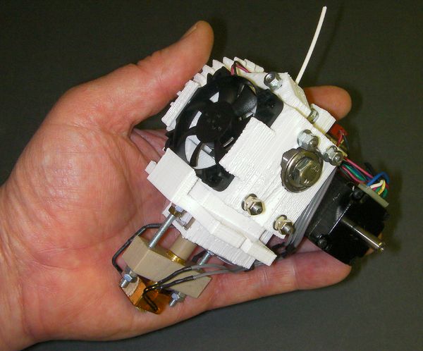
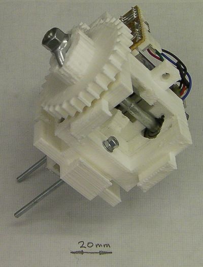
This printable extruder is intended to work on RepRap Mendel, RepRap Huxley, and virtually any other open-source 3D printer you can find.
It features:
- 1.75 mm filament
- Adaptable mounting plate to attach it to virtually any 3D printer
- Very compact high-torque NEMA 11 motor
- Active ducted fan cooling for high reliability
- Wade-style hobbed bolt filament transport
- Wing-nut drive to spread the torque loading on the plastic gears
- Push-fit hot-end parts - no thread cutting
- Easily replaced PTFE liner for the hot end
- A single M3-threaded rod cut to lengths makes all the fixings
- Lightweight: 420g (about 60% the weight of this extruder)
- Compact design (110 mm x 90 mm x 80 mm)
I based this design (loosely) on Jstkatz's extruder on Thingiverse, in particular, the idea of using a lever to trap the filament against its drive.
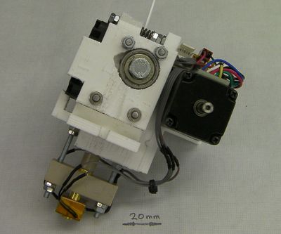
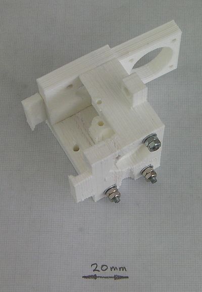
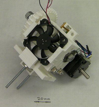
Front view
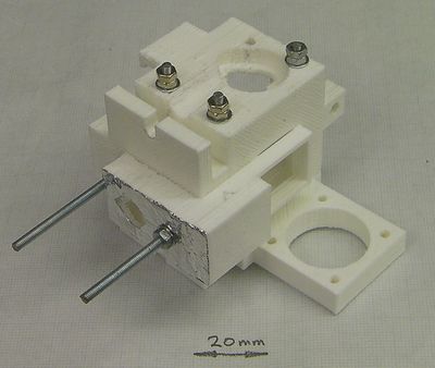
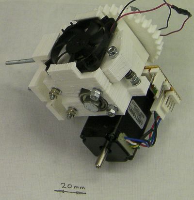
Rear view
OpenSCAD design.
Bill of materials
All the design files for the extruder are here in the repository. The OpenSCAD models are in the file universal-1.75mm-filament-extruder.scad. You will also need the files library.scad, parameters.scad, Design-drawings/bearing180.dxf and Design-drawings/bearing360.dxf.
The (very simple) Eagle circuit diagram is in Design-drawings/extruder.sch and the drawings of the hot-end components are in Design-drawings/hot-end.dxf.
Here is the OpenSCAD rendering of the reprapped components. You will need one each of the above.
The base-plate design shown above is for Mendel (both standard and Prusa). It is easy to adapt for virtually any RepRap and RepRap-like machine, though. The only critical things from the extruder's perspective are the 8.5mm hole for the PEEK insulator, the two 3mm holes 28 mm apart for the tie-rods that retain the hot end, and the support clip for the fan. As long as those are in the right place and there is space for the air duct to pass through, just about all the rest of the plate can be anywhere, with fixing holes wherever you like. Any plate you design needs to be 11 mm thick for the duct to fit under it.
Here is the complete bill of materials:
| Item | Type | Quantity | Notes/sources |
| Fixed block | reprapped | 1 | |
| Duct 1 | reprapped | 1 | |
| Duct 2 | reprapped | 1 | |
| Motor plate | reprapped | 1 | |
| Lever | reprapped | 1 | |
| Motor plate clip | reprapped | 1 | |
| Driven gear | reprapped | 1 | |
| Base plate | reprapped | 1 | |
| Motor spacer | reprapped | 1 | |
| Drive gear | reprapped | 1 | |
| NEMA 11 motor | electrical | 1 | http://www.slidesandballscrews.com/sy28sth510956b-p-362.html?cPath=45_90 |
| 12v 40mm 2-wire fan | electrical | 1 | ebay |
| 100 K glass bead thermistor | electrical | 1 | http://uk.rs-online.com/web/5288592.html |
| 6.8 ohm vitreous power resistor | electrical | 1 | http://uk.rs-online.com/web/0152280.html |
| 4-way pin header | electrical | 4 | |
| 2-way pin header | electrical | 1 | |
| 4-way header socket | electrical | 4 | |
| 2-way header socket | electrical | 1 | |
| 1k resistor | electrical | 1 | |
| 3mm LED | electrical | 1 | |
| 2.54mm stripboard | electrical | 13x8 holes | |
| 8mm diameter PEEK rod | mechanical | 40mm | http://uk.rs-online.com/web/0514776.html |
| 10x10x34 PEEK block (3/8” thick is fine) | mechanical | 1 | |
| 10x16x12.5 brass block (3/8” thick is fine) | mechanical | 1 | |
| 8mm diameter brass rod | mechanical | 35mm | |
| 2.2mm internal dia. Thin-walled PTFE tube | mechanical | 80mm | http://www.adtech.co.uk/TubeSize2.html – STW12 |
| 3mm (1/8”) internal diameter brass tube | mechanical | 50mm | RC model shops |
| 80mm M6 bolt | mechanical | 1 | |
| M6 wing nut | mechanical | 2 | |
| M6 washer | mechanical | 1 | |
| 626 bearing 6x19x6 | mechanical | 2 | |
| 623 bearing 3x10x4 | mechanical | 1 | |
| spring - wire: 1mm, id: 4mm, L: 12mm | mechanical | 1 | |
| 30mm M3 cap screw | mechanical | 1 | |
| M3 threaded rod 40 mm long | mechanical | 1 | |
| M3 threaded rod 55 mm long | mechanical | 4 | |
| M3 threaded rod 70 mm long | mechanical | 2 | |
| 12mm M2.5 screws | mechanical | 4 | |
| M3 washers | mechanical | 13 | |
| M3 nuts | mechanical | 30 | |
| Fire cement | mechanical | 1 ml | |
| 12mm Kapton tape | mechanical | 100mm | |
| 15mm M4 cap screws | mechanical | 2 | For attaching to the Mendel X carriage (standard or Prusa) |
| M4 washers | mechanical | 2 | For attaching to the Mendel X carriage (standard or Prusa) |
10mm PEEK sheet costs silly money, but it tends to be sold in quite large sizes and you only want a very small piece. Lots of RepRap suppliers sell it in small quantities.
The PTFE sleeve above is the one I used. Adtech's STW13 tube would probably work as well (or better), but you may have to change the diameter of the 2.5mm hole down the brass and PEEK for that. You want a snug, but easy-sliding, fit. Drill test holes incrementing up by 0.1mm in diameter in a scrap piece of brass to find the right size if you use a liner different to the one I used.
Make sure you get an M6 bolt, not a screw. On a bolt the thread only comes a short way up the shaft (20mm in this case); the rest is smooth.
The NEMA 11 motor above is the one I used, and I know that works. It doesn't have the highest torque of the range, but its torque curve against stepping frequency is pretty high, and - equally importantly - nice and flat. Other motors may well work too - this one doesn't run hot (35oC), so I suspect weedier ones might be all right. If you find a motor that works, add it to the alternatives section at the end below.
The fan I used was 7mm thick. But some 40mm fans are 10mm thick. The OpenSCAD model for this extruder has the fan thickness as a parameter, so you can print the parts corresponding to your fan.
A useful tool
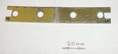
Most of the nuts in this design are in pairs as double lock-nuts. You will need spanners, of course. But most spanners are thicker than the nuts they fit. You may find it useful to get an old bit of sheet steel the same thickness or thinner than a nut and cut your own spanner with a hacksaw and small file. I used a straightened-out shelf bracket - M3 nut size at one end, M4 at the other. For this extruder you only need the M3.
The hot end
Start by building the hot end.
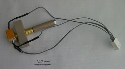
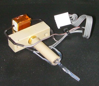
The hot end has a brass nozzle with a brass heater block containing a 6.8 ohm heating resistor and a temperature sensing thermistor. The brass nozzle has a PEEK insulator inserted into its top, and a PEEK block. The block has two M3 threaded rods running through it. These attach the hot end to the rest of the extruder. A thin PTFE liner runs down the central hole in the device, stopping about 12 mm from the bottom. The last section has no liner so that heat can conduct into the polymer more quickly.
Here is a picture of the hot-end components, and...
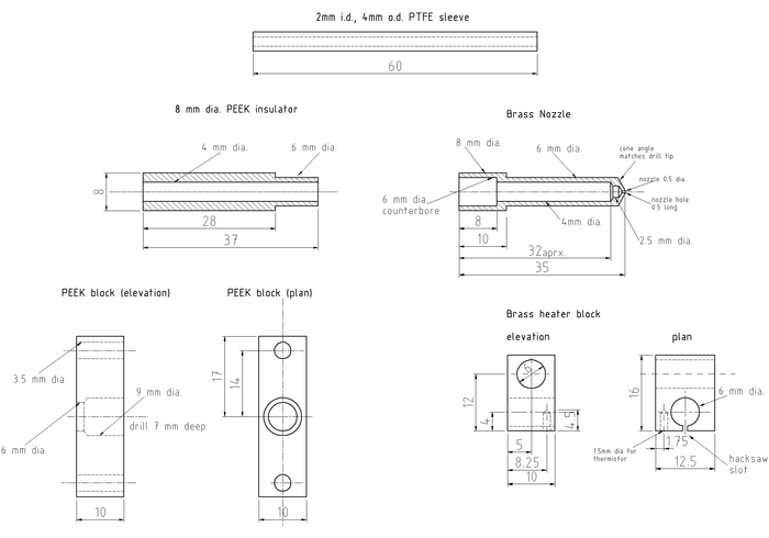
... here are the drawings for them. You could almost certainly make the nozzle and block from aluminium rather than brass. But don't use two different metals: if you do thermal expansion will cause the heater block to work loose.
Start by making the PEEK block. This is pretty straightforward. To get the 7mm deep hole, I just mark 7 mm on the side of the drill flutes with a felt-tipped pen. That is, 7mm in from the point of the tip. Make sure you can see your mark when the drill spins...
You will see that the holes for the threaded rods are 3.5 mm in diameter, even though the rods are M3. You want them to be a loose fit.
Next make the heater block. I hacksawed this roughly from a 3/8" sheet of brass, which is 9.5mm thick, not 10. Then I filed it square and drilled the holes. Clamp the block in the drill vice and support it underneath with a sacrificial piece of wood - you don't want it twisting as you drill it. None of the dimensions are critical. Make the hacksaw split on the 6mm hole last of all, and file away any burrs from the edges.
Next turn the nozzle. Face off the ends, then mark the centre with the finest centre drill you can find. Drill the 0.5mm nozzle hole about 4 mm deep. Use a woodpecker cycle - every 0.5 mm or so withdraw the drill to clear the swarf. Thake real care drilling this hole. ).5mm drills are not strong...
Turn the cone on the end. Take this just far enough back to obliterate the centre-drill mark you made. Run a fine file over the outer edge of the cone to round it off. You will probably find that you have also obliterated the end of your 0.5mm hole. Open it up again by hand with the 0.5mm drill held in a pin chuck.
Turn down the 6mm shaft. As you near the right diameter keep stopping and check it repeatedly against the 6mm hole in the heater block. You want an interference fit - don't go to far.
Turn the nozzle round in the chuck, so it is held by that 6mm shaft. Turn down the 8mm end.
Mark the centre and drill the 6mm counterbored hole with an ordinary twist drill 8 mm deep.
Drill the 2.5mm hole about 10 mm deeper - not all the way to the end.
If you have a 6mm slot drill, you can use that to finish the counterbore. If not, grind an old 6mm drill flat as described here and use that.
Take the nozzle out of the chuck and hold the 2.5mm drill beside it. By eye line the tip up so that it's about 0.5mm in from the nozzle tip. Mark the drill at the other end with a felt-tip to coincide with the end of the 8mm section. Beware parallax. Look at what you have done, and make sure you remember the relation between your mark and where the drill will have to sink to. Put the drill in the tailstock and carefully drill to your mark. You will probably find that this has again blocked the 0.5mm hole. Holding the nozzle tip upwards (you want swarf to fall out of the big end) clear it by hand, as before. Twist a big drill by hand against the 6mm hole to chamfer the edge, again with the tip pointing up.
Finally make the PEEK insulator. Again, when turning the 6mm section, check it repeatedly against the 6mm hole in the nozzle. You want a tight fit that you can just push by hand. PEEK gets very hot with friction when machined, especially when drilled. Again use a woodpecker cycle for the 2.5mm hole, and give the drill and the PEEK plenty of time to cool between drilling.
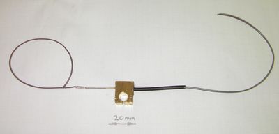
Retain the resistor inside the heater block with fire cement or high temperature epoxy. Make sure that whatever you use is rated up to 250o C. Don't cut the resistor leads - leave them full length. Crimp wires onto the ends of the resistor leads using bootace ferrules or similar (shown left). Don't solder the wires - the solder won't stand the temperature.
Put heat shrink over the join (shown right). If you do this while the fire cement or epoxy are still unset, you can push the heatshrink a little way into it. When the fixative is set and the heatshrink shrinks, this will make a very neat join. Don't bother to heat the heatshrink - when you operate the nozzle the heat will do this for you.
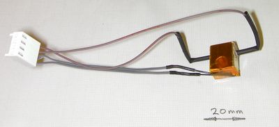
solder two leads onto the thermistor. I put PTFE sleeving taken from PTFE-insulated wire on the thermistor leads themselves. If you do this, only take one leg's insulation right up to the thermistor; leave the other short by about 3 mm. If both pieces of insulation abut the thermistor, they will put a strain on its leads as they are a little to thick to fit in the gap.
Wrap a 10mm square of PTFE plumber's tape round the thermistor itself, then insert it in its hole.
Secure it with Kapton tape wrapped round the block as shown. The tape runs right over the hole down which the nozzle will fit.
Cut the discs of tape from that hole with a scalpel.
Put the PEEK block on the brass nozzle, and then put on the heater block. If need be, stand the heater block on a short length of tube (15 mm plumbing pipe works well) and tap the nozzle through it with a soft hammer. You want a tight fit for good thermal contact. The tube is to stop the point of the nozzle getting damaged.
Push the PEEK insulator into the back, then gently push the PTFE sleeve down the device as far as it will go. Withdraw it about 10 mm and make a mark with a felt-tip pen where it enters the PEEK insulator. Withdraw it fully, match up your mark, and make sure that the liner has gone down to about 10 mm from the tip of the nozzle. Cut it to length about 20mm above your mark. Put it back in up to the mark.
Now, using a very sharp blade, split the end in three down to the mark, like three petals. Fold these back and down the outside of the PEEK insulator.
When you assemble the device, these petals will be trapped between the extruder drive body and the PEEK insulator. This holds the PTFE in place.
Assembly
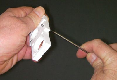
Sink four M3 nuts in the holes in the motor plate. Use a short M3 screw and washer to pull them into place. Make sure the hexagons line up before you pull.
Offer up the clip to the motor plate, and the two halves of the duct to each other. Trim away any excess plastic with a blade to ensure a snug fit.
Arrange a couple of clamps to hold the parts while they set, glue them with superglue, and clamp them. The triangular lip of the clip points away from the nuts you just fitted in the motor plate.
A piece of polythene plastic bag under the clamps will ensure that they don't glue to the work...
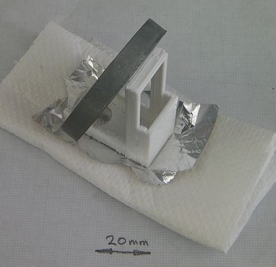
When the duct is set, glue aluminium kitchen foil onto the bottom of it. Weight it onto something soft to get the foil well pushed against the duct. The aluminium is a heat reflector. Cold air will be running on the interior of the duct, and the foil helps keep the whole thing cool from both the extruder hot end under it, and any heated bed that you may be using. When the glue is set, trim the foil round the edges and from the holes.
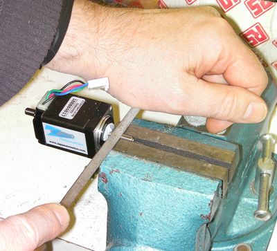
If your NEMA 11 motor has a round shaft, file a flat on it. Put Blu-tack into the gap between the motor shaft and the motor body to keep filings out of the motor's bearing. Fit the drive gear on the shaft so that the ends coincide, and note roughly where the flat needs to be. Take the gear off. Clamp the shaft (not the motor body) in a vice and file the flat. If you use a small file you can see when the flat is parallel with the shaft axis - it makes a rectangle. A trapezium means you've filed at an angle.
Put lock nuts on the ends of three of the 55 mm M3 threaded rods. Put washers under them and use them as long screws to attach the motor plate to the fixed block. Do them up firmly but not too tight - remember you're assembling a plastic object, not a steel one.
Put lock nuts on the end of one of the 70 mm M3 threaded rods. Put a washer under them and use this to attach the base plate to the fixed block at the side where the fan will go. Put two nuts and a washer on the bottom end, but don't do them up tight yet.
Push the other 70 mm M3 threaded rod up through the holes at the back where the diagonal air passage runs through the fixed block. Drop a washer over it and put two nuts on it. Lock them against each other at the top of the thread (this can be a bit fiddly - I used two pairs of long-nosed pliers). Run a washer and nuts up the other end from the bottom.
Tighten up the two rods.
Put the air duct over the second rod and secure it with a nut and washer.
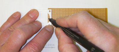
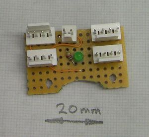
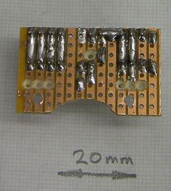
Use the motor spacer as a template to mark out two 2.5mm drill holes and a curcular dent in a piece of stripboard. The stripboard wants to be 13 holes by 8, with the strips going in the short direction - see below. Drill the holes and file away the circular dent.
Break the strip tracks as shown and solder on the connectors, the 1K resistor and the LED. You will also need to run a couple of fine insulated wires to connect one end of the LED and one end of the fan connector.
Mark the end of the motor shaft with a felt-tipped pen so you can locate the flat you filed on it when that flat is under the drive gear.
Put an M3 nut in the slot in the drive gear and loosely put a 12mm M3 set/grub screw through it. Make sure that the grub screw does not yet poke into the 5mm motor shaft hole.
Put the drive gear on the stepping motor's shaft. Tighten the set screw to hold it firmly. Mark the gear next to your mark on the motor shaft. That way you will be able to see if it works lose after long usage.
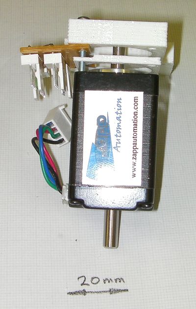
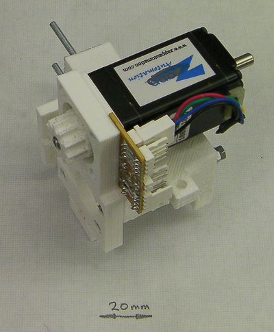
Mount the NEMA 11 stepping motor, the stripboard, and the motor spacer to the motor plate with four 12mm M2.5 screws.
Cut the motor leads to length and put a 4-way socket on them. Allow a little slack, so you can plug and unplug the socket.
Put the 626 bearings in their holes either side of the extruder and put the 80 mm M6 bolt through them. Put a washer on the gear end.
This shows the sequence of components down the bolt. I used an M6 hex nut on the end, but another wing nut the other way round would be better - it will allow you to take the gear off and put it back on more easily. I'd recommend that (and it's in the bill of materials above).
Push the M6 wing nut into the top of the gear and screw both onto the bolt. When the gear engages with the motor you may find it simpler to turn the head end of the bolt than the gear. Put a lock nut on the wing-nut end.
Do everything up finger tight.
Push a short length of filament down through the extruder and mark either side of it on the bolt with a felt-tipped pen.
Dismantle the bolt, gear and associated components so you can hob the notches on the bolt that will drive the filament through the extruder.
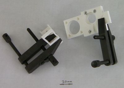
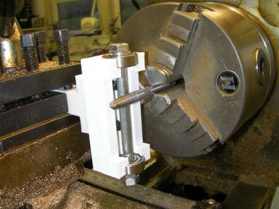
The hobbing jig is designed to fit in the toolpost of a lathe, with an M4 tap in the lathe chuck to do the hobbing. But it should be possible to set things up with a clamp and a vice, and to do the hobbing with an electric drill instead.
Put two 30mm M3 cap screws through the slots in the hobbing jig and use them to attach the handle.
Carefully extend your filament marks on the bolt so they go right the way round.
Put the bearings and the bolt in the hobbing jig. Clamp the jig and offer the bolt up to the M4 tap. Measure how far out your felt-tip marks either side of the filament are from the centre-line of the tap.
Take everything apart and carefully slide the hobbing jig handle in its slots through that distance to get everything aligned. You may find it helps to measure from the original positions of the handle screws and make a mark where you want them to end up.
Put everything back together and tighten two M6 nuts on the bottom of the bolt to lock it. It should freely rotate in the bearings.
If you have it, smear some Trefolex cutting compound on the tap and the bolt where they will touch.
To do the hobbing you want the drill or the lathe on its slowest turning speed.
Move the bolt against the tap and let the tap turn the bolt. Move it in another small amount.
Each time you push the bolt against the tap, leave it for a while to cut freely.
You want to cut just deep enough that the root of the tap threads is just cutting the bolt. This will reduce the bolt diameter a tiny fraction there, but you don't want to make a big dent.
When you have finished you may find that you can't get the bearing on the bolt's head end off past the hobbing. This doesn't matter - that just becomes the bearing at that end of the bolt in the finished extruder...
Clean any swarf and cutting compound thoroughly off the bolt. Put everything back together finger tight.
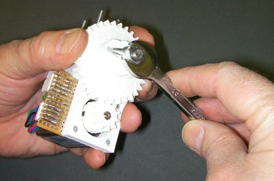
This picture shows the M6 lock nut being tightened with a spanner. Don't do this yet (you need to take the bolt assembly off again to attach your extruder to your RepRap). But - when you do - always tighten the nut by holding the big gear as shown above. That way the torque from the spanner is not transmitted to the rest of the extruder.
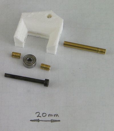
Next assemble the lever. You will need an M3 nut in addition to the parts shown above.
I found that the cleanest and most accurate way to cut the 3mm internal-diameter brass tube was to use a plumber's pipe cutter. This seems a bit of a sledgehammer against the nut of the tube, but it works well. But, if you do use a pipe cutter, it will reduce the end diameters slightly. Open them out again by running a 3mm drill down the tubes. Clean away any burrs with a file.
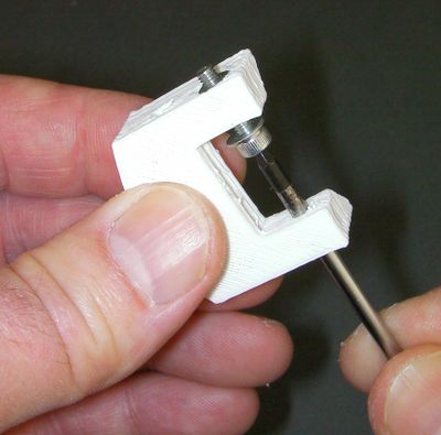
Put the nut in the end of the lever using the same technique that you used for the motor plate above. You should find that an M3 allen key fits down the opposite hole in the lever, as shown.
Assemble the M3 screw, brass tubes and bearing. Push the longer brass tube through the 4mm hole in the lever.
Next put the fan in the extruder. Cut the leads to length (again, leave a little slack for plugging and unplugging), and put a two-way socket on the ends.
Put the lever in its slot. Put two M3 nuts on the end of the final 55mm length of M3 threaded rod, put a washer under them, and use the result as a screw to pass through the long brass tube in the lever. Do this up firmly, but not so tight that you draw the sides of the extruder together and trap the lever.
The 40 mm M3 threaded rod is the screw-adjuster that applies pressure to the filament via the bearing on the lever.
The trick with getting this in place is to do the assembly through the little post at the motor side of the extruder. Put an M3 nut in this post and screw the 40 mm rod a little way into it. Push a washer, and then the spring, into the hole in the lever - it helps to put a spare M3 screw through from the other side temporarily.
Put two more nuts, then a washer, onto the 40 mm rod. Screw it right through, running all the nuts down it as you go and withdrawing your temporary guide screw, until it pokes about 6mm out the far side of the lever.
Put two lock nuts on that end and tighten them against each other. These are to give you something to hold to adjust the lever pressure.
Finally, put some filament through, and position the two middle nuts so that the spring is just relaxed. Lock them together.
The extruder is now finished. As mentioned above, when you fix it to your RepRap you will have to take the big gear off to get the two 15mm M4 screws that hold the extruder's base plate to the RepRap's X carriage in place.
When you put the big gear back on don't forget to hold the big gear when you tighten the M6 nut against the wing nut to lock it.
<videoflash type="vimeo">22485769</videoflash>
Here's a video of the extruder working. It is, of course, printing itself...
Speeds
With 16-microstep stepper driver electronics I set the number of steps per millimeter of filament extruded to 28. This gives very good prints with a maximum deposition speed set to 2500 mm per minute. I set the dwell at the start of extrusion to 50 ms. I expect that the extruder would work faster, though I haven't tried it, as I'm more concerned with quality than speed.
Maintenance
To put filament in the extruder for the first time, just run it down through and then tighten the lever adjuster. Don't do it too tight.
Renew the filament supply when the extruder is hot. Slacken off the lever, then pull out the old filament. Push the new filament in and tighten the lever as above.
Occasionally take the M6 bolt out and check it. It should be clean. If there is filament powder on the hobbed grooves then the device is slipping and abrading the filament. This means you need to run it slower (i.e. at fewer mm/minute when building).
Alternatives and improvements
This is the place to add alternatives and improvements to this design.
