This page is under construction! Sorry for inconvenience.
Introduction
Welcome on the building manual page of ToyREP 3D Printer. On following pages you will find step-by-step walkthrough the construction of the printer, wiring electronics, firmware settings and calibration, so you can achieve the best performance of your printer.
Warning
Most of the pictures were taken after construction of first prototype. Some nuts, or other vitamins are already glued or attached to their position. There are also few minor changes described in text against what you can see on the pictures. If you are not sure what to do, please follow the text or contact me on thorgal(at)atlas(dot)cz.
Please read the complete manual before you will even order any parts or start construction works.
Disclaimer
I am sorry for any mistakes that may appear in any documentations for the printer and would like to ask you kindly to give me a notice of any problem you will find on thorgal(at)atlas(dot)cz. Despite my genuine regret I cannot be held responsible for any loses or injuries caused by assembling or operation of the ToyREP 3D printer.
Preparations
Print the parts as per your desired size and functions of the printer. You can collect them at Thingiverse.
The prototype was printed from 3mm thick ABS with 0.5mm nozzle, 0.25mm thick layer, 2 outlines, 3 top and bottom layers, 30% hexagonal infill. Total consumption of plastic is in the BoM. You can use your own proven setup. Only ABS is highly recommended to follow up as some parts will get quite hot.
Printed parts should be cleaned form residual and overflown plastic. Clean the holes For M3, M4 and M8 Threaded rods, screws and nuts.
Before the assembly, all parts suggested by the BoM should be collected.
Tools
- Drills of diameter 2mm, 3mm, 4mm, 5mm, 8mm
- Needle Files
- Phillips screwdriver of right size (or other, if you use different screw heads)
- Pliers
- Two wrenches No.13 for M8 Nuts.
- Cutter or scissors
- Tweezer
- Calliper
- Soldering Iron
Construction
PSU Cover
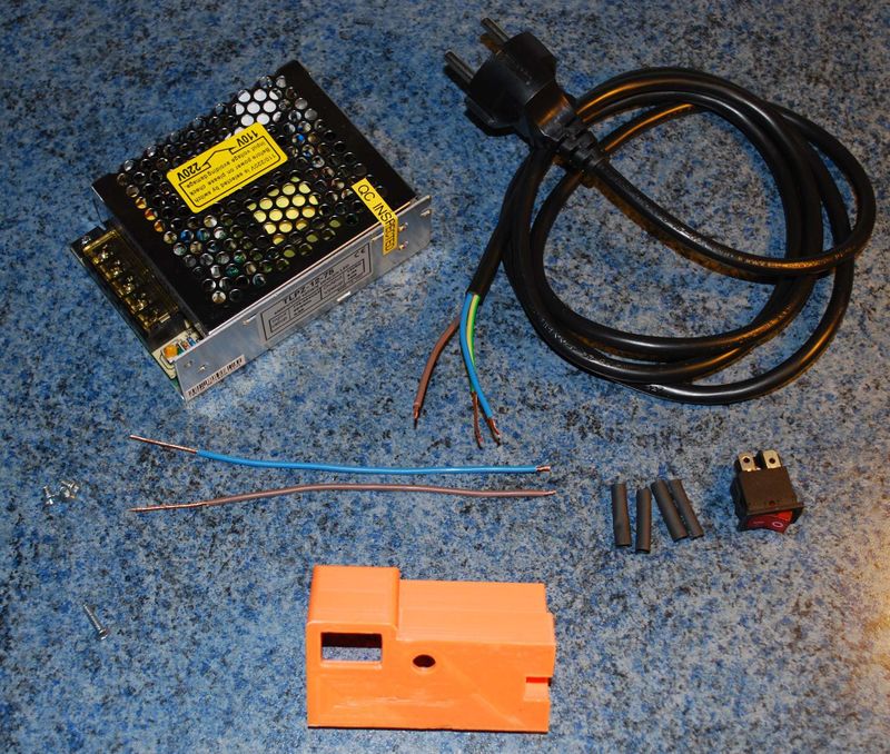
Part required for PSU cover
| Picture
|
Quantity
|
Description
|
Comments
|
 |
1 |
PSU Cover |
Chose PSU1.stl (111x78x36mm big PSU) or PSU2.stl (129x99x38mm big PSU)
|
| |
1 |
1.8m Power Supply cable with plug |
cca 1.5-2mm long PC cable would be just fine - cut of the computer Euro connector, keep power socket plug.
|
| |
1 |
200mm Dual Line cable |
Should be able to withstand at least 12V 4A, Insulation with two colours to distinguish +12V and -12V
|
| |
1 |
Power supply switch (250V, 1A) |
Installation into panel with mounting hole 13x19mm
|
| |
4 |
Ø6mmx25 Heat Shrink |
|
| |
1 |
3X13 Round-pan Wood Screw |
|
| |
1 |
Cable Tie |
|
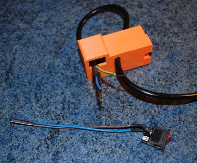 Cut off the Euro connector from PC Power cable. Cut off another 150mm piece of cable. Remove the outer insulation from the 150mm long piece, so you will get separate wires. Remove insulation on all the ends of cables. If you have switch, that support L and N wire switching solder both brown and blue 150mm long wires to separate circuits of the switch. Otherwise switch only L (brown). Protect the joint with heat shrink. Pull the Power cable through the cover. |
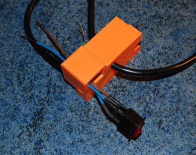 Put heath shrink on wires (L and N) of the power cable. Solder power cable to the switch. Respect L and N circuit! Check the circuit with multimeter if required! Shrink the heatshrink. Pull the wires through switch hole. |
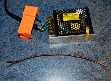 Prepare piece of Dual Line DC power cable. The cross section of wires should be at least 1mm². Remove the insulation on the ends. |
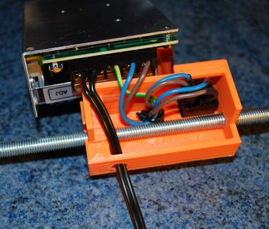 Insert smooth rod into the cover. Bend the wires around it, so you can place the cover on PSU. Put zip tie on the end of power supply cable. |
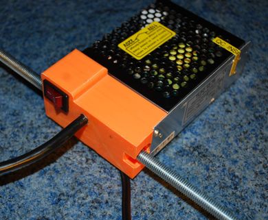 Attach the cover to PSU by 1 pc of 3x13mm round head wood screw. |
Bottom X Rods
| Picture
|
Quantity
|
Description
|
Comments
|
 |
1 |
PCB Mount |
Chose PCB1-1.stl for PSU1 or PCB2-1.stl PSU2.stl for PSU2
|
 |
1 |
PCB Mount |
Chose PCB1-2.stl for PSU1 or PCB2-2.stl PSU2.stl for PSU2
|
| |
2 |
M8x255mm Threaded Rod |
Alternatively 265mm long for PSU2 and/or 125x125mm print area or 240mm for printer with 100x100mm print area and without PSU.
|
| |
1 |
M8x245mm Threaded Rod |
Alternatively 265mm long for PSU2 and/or 125x125mm print area or 230mm for printer with 100x100mm print area and without PSU.
|
| |
6 |
M8 Hex Nut |
|
| |
6 |
M8 Washer |
|
| |
3 |
M3X10 Countersunk Screw |
|
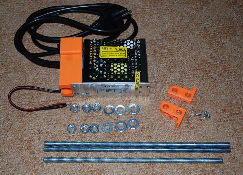
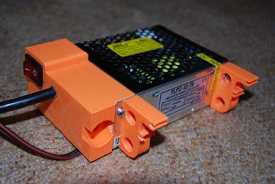 Install PCB mounts on PSU by M3x10 countersunk screws. |
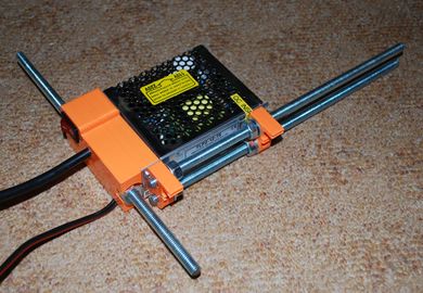 Put two M8x255mm threaded rods through PCB mounts with nuts and washers between the mounts but but do not go too far over the cover. Pull one M8x245mm rod and in the hole in PSU cover place washer over nut. |
Bottom Z Frame
| Picture
|
Quantity
|
Description
|
Comments
|
 |
1 |
Left Z Motor Mount |
|
 |
1 |
Right Z Motor Mount |
|
| |
2 |
28BYJ-48 Stepper Motor |
Length of wire c. 120mm and 180mm
|
| |
2 |
Ø8x295mm Smooth Rod |
|
| |
1 |
M8x245mm Threaded Rod |
Alternatively 265mm long for PSU2 and/or 125x125mm print area or 230mm for printer with 100x100mm print area and without PSU.
|
| |
8 |
M8 Hex Nut |
|
| |
38 |
M8 Washer |
Additional washer are used to set correct distance between plastic parts. The amount can vary.
|
| |
1 |
M3x90mm Threaded Rod |
|
| |
4 |
M3 Hex Nut |
|
| |
1 |
M3 Washer |
|
| |
4 |
3X13 Round-pan Wood Screw |
|
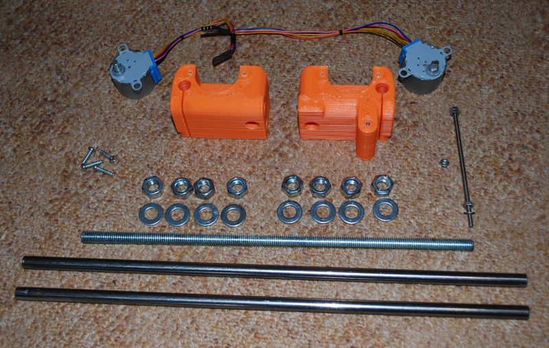
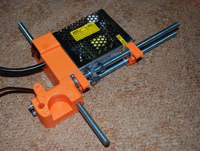 Place sufficient amount of M8 washers between PCB mount and Right Z motor mount. Pull through the X axis threaded rods. Only 6-10mm should protrude. |
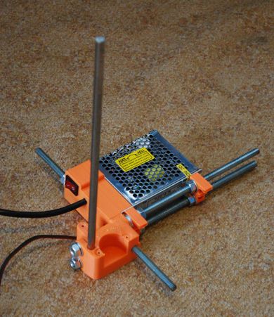 Install one smooth rod into right motor mount and tighten right side. |
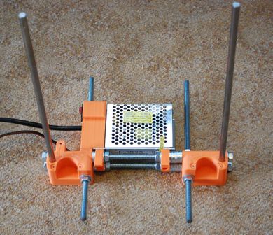 Do the same on left Z side. |
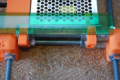 Distance of Z1 and Z2 part should be 120mm for PSU1, 135 for PSU2 and/or 125x125mm print area. Without PSU is distance reduced to 105mm. |
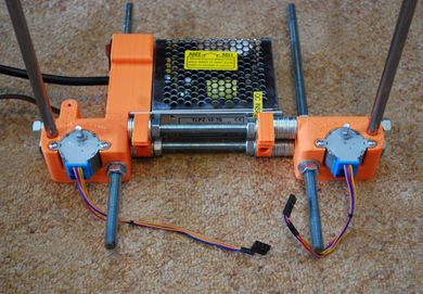 Put Y axis threaded rod also into left Z motor mount and place M8 nuts and washers around it. Do not tighten Y threaded rods yet. Install both Z motors. Shorter wire goes to the right side (left on this picture). |
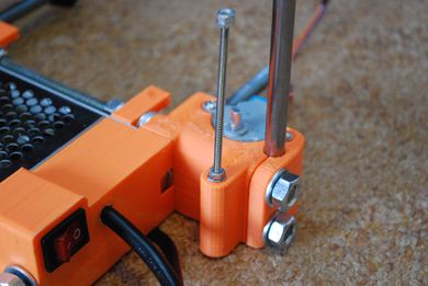 Place one M3 nut into hexagonal hole in right Z motor mount. Install Z endstop distance rod. Two M3 nuts should make the head while one M3 nut and washer and the bottom serves to fix length. |
Rear Y Frame
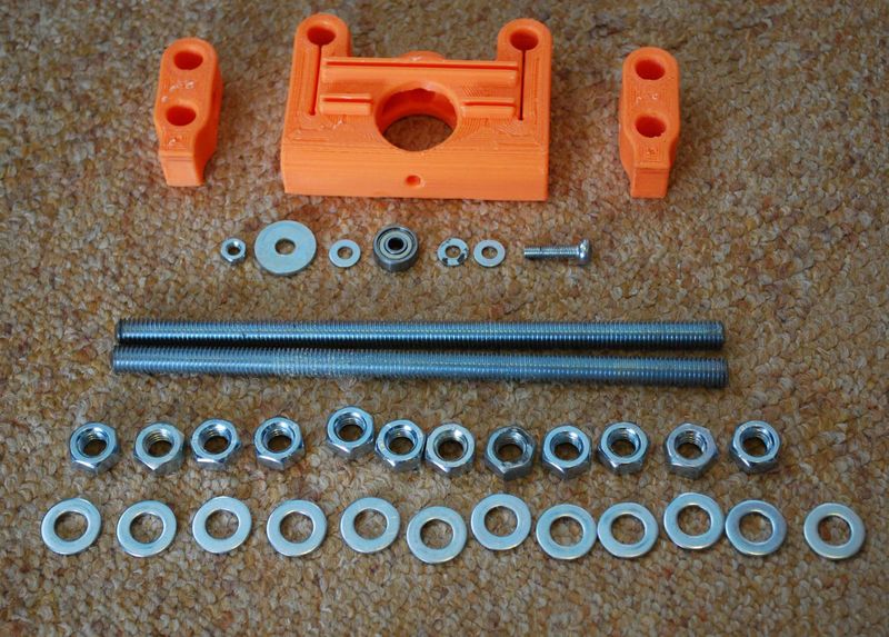
Parts for rear Y axis frame
| Picture
|
Quantity
|
Description
|
Comments
|
 |
1 |
Rear Y Axis Bearing Mount |
|
 |
2 |
Y Frame Corner Leg |
|
| |
1 |
624ZZ Ball Bearing |
|
| |
2 |
M8x170mm Threaded Rod |
Alternatively 180mm long for PSU2 and/or 125x125mm print area or 155mm for printer with 100x100mm print area and without PSU.
|
| |
12 |
M8 Hex Nut |
|
| |
12 |
M8 Washer |
|
| |
1 |
M4x20mm Round-pan Screw |
|
| |
1 |
M4 Hex Nut |
|
| |
3 |
M4 Washers |
|
| |
1 |
M6 Mudgard Washer |
|
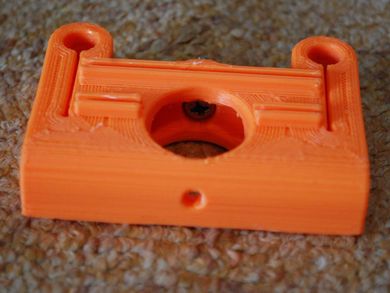 Insert M4 Screw from inside of the Y1 part. |
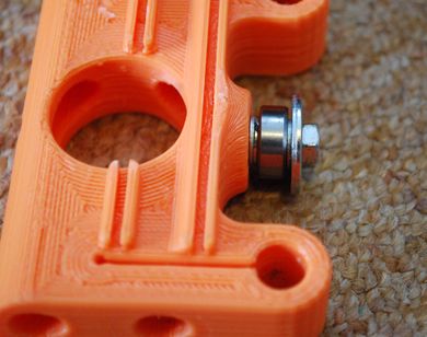 Place two M4 washers, 624ZZ bearing, M4 Washer, Mudgard washer and tighten with M4 nut |
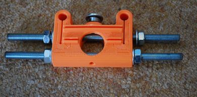 Pull M8 threaded rods through Y1 plastic part. Bottom rod should be fixed and centred. Upper one keep loose. |
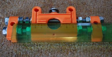 Place legs on the ends so the distance between them is the same as between Z1 and Z2 motor mounts. Tighten them on bottom and upper rod. |
Front Y Frame
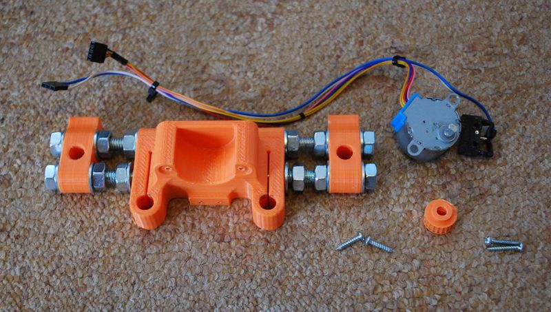
Parts for front Y axis frame
| Picture
|
Quantity
|
Description
|
Comments
|
 |
1 |
Front Y Axis Motor Mount |
|
 |
2 |
Y Frame Corner Leg |
|
 |
1 |
T2.5 Timing Belt Pulley |
|
| |
1 |
28BYJ-48 Stepper Motor |
Length of wire c. 250mm
|
| |
1 |
Micro Switch |
Mounting holes Ø2.5mm 11mm apart, length of wire c. 280mm
|
| |
2 |
M8x170mm Threaded Rod |
Alternatively 180mm long for PSU2 and/or 125x125mm print area or 155mm for printer with 100x100mm print area and without PSU.
|
| |
12 |
M8 Hex Nut |
|
| |
12 |
M8 Washer |
|
| |
2 |
3X13 Round-pan Wood Screw |
|
| |
2 |
2.5X13 Round-pan Wood Screw |
|
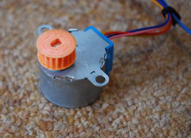 Place pulley on the motor |
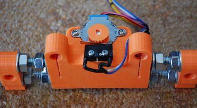 Prepare front Y frame the same way as the rear one. Install motor and micro switch by 3x13 and 2.5x13 wood screws. |


