BIQ Opto Endstop
Release status: working

| Description | Revision 0.1
|
| License | CC BY-NC-SA 3.0
|
| Author | |
| Contributors | |
| Based-on | [[]]
|
| Categories | |
| CAD Models | Eagle
|
| External Link |

Contents
Introduction
RepRap compatible Opto End-stop using an Opto End stop with a 0.5mm beam slightly smaller than the HB102 beam width of 0.8mm.
The opening of the interrupter is 5mm allowing for a 3mm black perspex interrupter tag designed for use on Huxley Seedling but can be used on All RepRaps.
The output of all three versions is an Open collector active High signal.
Active high means a 1 is made when the end-stop is triggered.
Project goal was to Design:
A small low cost PCB < £1.00 for 3 bare PCBS.
Low cost of components.
With a smaller beam to break.
Wider opening for a 3mm interrupter and little more clearance.
Three circuit build configurations. ECO, standard, and Illuminated.
Reprap Standard mounting centres. (holes)
PCB size is 25.5mm x 10mm metric or 1.004" x 0.394" in Imperial
- You'll need a soldering toolkit to do most of this.
- Read the Electronics Fabrication Guide if you're new.
Get It!
Mouser project parts list for BiQ opto end stop eco
Mouser project parts list for BIQ opto end stop illuminated
Mouser project parts list for BiQ opto end stop standard
Mouser project parts list for Basic opto end stop
Full Kits
Master Schematic of board

Master CCT of the PCB.
Files
You will be able to once I have made them and uploaded them. = to download the electronics files from GitHub BIQ Opto Endstop.
This file contains the following:
   PDF files of the schematic, copper layers, and silkscreen
   Eagle source files for modification
Schematics
ECO Schematic
(easy to build Discreet components)
The Led is on all the time for setting up your end-stops.
Once the RepRap is set-up the link can be removed as you do not need to see the led going off/on.
In the same way your scanner or paper printer has not got a Led on its end stops.
An open collector drive gives better noise immunity.
(however adding a 10K surface mount pull up resistor is an option.)

Standard Schematic
(more difficult to build Discreet components with one Surface mount resistor)
The Led is off all the time and is only activated when the end stop is triggered.
This gives the same function as most of the other RepRap end stops.

Illuminated Schematic
(difficult to build Discreet components with two Surface mount resistors)
The Led lights only when the end stop is triggered.
Its function can also be enabled and disabled by the link.
An open collector drive gives better noise immunity.

Components
Components ECO

Components STD

Components Iliminated

For illuminated version use the 470 ohm resistors.
For the Gen7 style circuit use the 1k and 2.2k resistors..
Soldering Instructions
Building 3 ECO PCBs

Solder 3 220 ohm resistors on the 3 boards. Note check the holes are the same size when fitting as there is a smaller via hole that you should not use.

Solder 3 450-470 ohm resistors on the 3 boards

place the 3mm Leds in position with the long led wire on the right side.
Stop and double check before you solder them the D shape of the plastic is how you write a D

Solder the 2 pin header at 45 degrees like a forward slash the left hole is marked with a circle and a line

Double sided plated through PCBs are difficult to re-adjust once all the pins are soldered.
Place the Opto devices in their positions Matching the S on the device to the S printed on the PCB.
Note the S in this build version is on the right side of the board
Before you solder check that the chamfered edge is near the middle of the board.
Then Solder the 2 pins near the bottom edge of the board.
Check the Opto devices are square and level before soldering the inner two pins.
You can now fit the Eco Link to enable or disable the Led.
Do not snap the PCBs apart yet
Now you can go to the common section for all three circuit configurations Wiring them up
Building 3 STD PCBs

Place the 3 10K ohm surface mount resistor and solder in place. I use a pair of tweezers to hold the device in place an solder one end.
Use the tweezers to adjust the position ready to solder the other end, ensuring it is flat.
Now solder the other end. repeat for the other two resistors
Now that's the difficult bit done. Well done if this was your first surface mount resistor

Solder 3 220 ohm resistors on the 3 boards. Note check the holes are the same size when fitting as there is a smaller via hole that you should not use..

place the 3mm red Leds in position with the long led wire on the right side.
Stop and double check before you solder them the D shape (Which is an elongated D shape on the red plastic Led's) is how you write a D
You can now Fit the 3 FET transistors they are also a D shape and the middle pin needs to be tweaked out slightly to fit the holes.

Finally
Double sided plated through PCBs are difficult to re-adjust once all the pins are soldered.
Place the Opto devices in their positions Matching the S on the device to the S printed on the PCB.
Note the S in this build version is on the right side of the board
Before you solder check that the chamfered edge is near the middle of the board.
Then Solder the 2 pins near the bottom edge of the board.
Check the Opto devices are square and level before soldering the inner two pins.
Do not snap the PCBs apart yet
Now you can go to the common section for all three circuit configurations Wiring them up
Building 3 Iluminated PCBs
Fit the 3 2k2 ohm Surface Mount resistors as shown .

Now fit the 3 470 ohm Surface Mount resistors as shown .

Solder 3 180 ohm resistors on the 3 boards it straddles the 470 ohm surface mount resistor.
Note 1 this must be a 180 ohm resistor in this configuration.
Note 2 check the holes are the same size when fitting as there is a smaller via hole that you should not use.

Note the boards the direction of the boards in this picture set.. is opposite way round to the Eco set picture
place the 3mm Leds in position with the long led wire on the right side.
Stop and double check before you solder them the D shape of the plastic is how you write a D.

Solder the 2 pin header at 45 degrees like a Back slash the left hole is marked with a circle and a line

Double sided plated through PCBs are difficult to re-adjust once all the pins are soldered.
Place the Opto devices in their positions Matching the S on the device to the S printed on the PCB.
In the pictures shown here the S is on the left side of the board.
Before you solder check that the chamfered edge is near the middle of the board.
Then Solder the 2 pins near the bottom edge of the board.
Check the Opto devices are square and level before soldering the inner two pins.

You can now fit the Led enable disable link on the two pin header.

Do not snap the PCBs apart yet
Wiring them up
Do not snap the PCBs apart as its easier to solder wires to them as a group of 3 or 6.
The connections on the PCB are arranged like this.
VCC 5v
Signal open collector active high signal
GND Ground
The PCB could have a 3pin header connector fitted straight or right angle style.
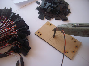
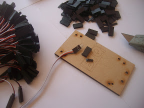
I prefer not to have connectors at both ends of the opto end stop wires. Thus saving on connector costs & connector faults.
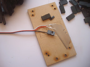
So I solder my wires directly to the pads on the PCB this can be on the top side or bottom side or even through the holes.
This picture shows all three methods

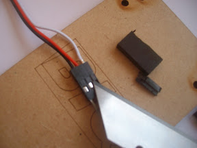
On most of the "New" Controller PCB designs the wires are arranged on the plug so that when connecting them up.
The connection is "mistake proof" This means if you plug them in wrongly you are less likely to kill the Opto end stop.
GND Ground
VCC 5v
Signal End stop input signal.
Servo extension leads bought from a Model shop saves making up 0.1 header plugs. Price of an extension lead is £1 ea or 69p if you buy a pack of 12.
The red black and white wired ones are the better colour scheme than the Orange Black and Brown wire versions you can use either.
For Huxley Seedling you need these wire lengths.
X sensor 250 mm
Y sensor 185 mm
Z sensor 130 mm
Pictorial guide on making leads for the BIQ opto end-stops.
Click a picture to enlarge
<a href="https://picasaweb.google.com/lh/photo/rANJCoa4VgDgi5wINgULzNMTjNZETYmyPJy0liipFm0?feat=embedwebsite"><img height="216" src="https://lh3.googleusercontent.com/-krj0WTqOMdY/T4GcQacc7kI/AAAAAAAAEGo/yqJCIYvJ1FY/s288/SANY1334.JPG" width="288" /></a><a href="https://picasaweb.google.com/lh/photo/cx0oDXyJeJn_mQE2kyTiH9MTjNZETYmyPJy0liipFm0?feat=embedwebsite"><img height="216" src="https://lh6.googleusercontent.com/-V2GptiBVOTk/T4GcRYwDCTI/AAAAAAAAEG0/h4IoRNQB-fk/s288/SANY1335.JPG" width="288" /></a> <a href="https://picasaweb.google.com/lh/photo/ES1hVeH23rf86ZPx4Oq1T9MTjNZETYmyPJy0liipFm0?feat=embedwebsite"><img height="216" src="https://lh6.googleusercontent.com/-okgs81_U3Lo/T4GcS509gwI/AAAAAAAAEG8/T8uwb7KrzlE/s288/SANY1336.JPG" width="288" /></a><a href="https://picasaweb.google.com/lh/photo/IRhb5lDTDtDNtcM3sUYCZtMTjNZETYmyPJy0liipFm0?feat=embedwebsite"><img height="216" src="https://lh6.googleusercontent.com/-8uUB6TCm9p0/T4GcUcSDQMI/AAAAAAAAEHA/j9hLtH_mSNY/s288/SANY1337.JPG" width="288" /></a><a href="https://picasaweb.google.com/lh/photo/vEoNm0zGb85lhKRIr8DovtMTjNZETYmyPJy0liipFm0?feat=embedwebsite"><img height="216" src="https://lh3.googleusercontent.com/-q7AJTvX-dQs/T4GcVeSsAII/AAAAAAAAEHI/5VdHxzI06O8/s288/SANY1338.JPG" width="288" /></a>
Oh how I wish posting some thing on the WIKI was as easy as posting to Blogger.
It is, but on this page you try hard to make it complicated. Simply accept default appearance and you're set. --Traumflug (talk) 01:22, 4 October 2014 (PDT)
Testing
You can now snap the PCBs apart.
File:BIQOptoendstopWireSnaped.jpg
Fitting
The holes on the PCB are pre drilled to 3.2mm this allows for slight differences in printed parts on a self replicated RepRap.
3mm nuts will not turn due to the position of the sides of the opto end stop case as with most of the other opto end stop designs.
On the Huxley seedlings frame X,Y and special Z fine position adjuster there are two 2mm square holes to tywrap the wires down to the frame.
On other RepRap builds its a good idea to tywrap the wires to the frame to stop the wires getting pulled.
File:BIQOptoendstopWirefit1.jpg
File:BIQOptoendstopWirefit2.jpg
File:BIQOptoendstopWirefit3.jpg
To be updated with BOMs, more files and more build pictures.
The pictures bellow show how I've managed to get the price per PCB down to a more sensible price point for an End stop.
These boards are know as Panellised PCBS the main reason for panelling them is the small size of each board

