挤出机组装
       介绍|搭建框架|组装Y轴|组装X轴|组装Z轴|组装热床|挤出机组装|热端组装|电源|布线|调试|打印
                                多颜色/多材料|维护|故障排除|改进
Contents
选择
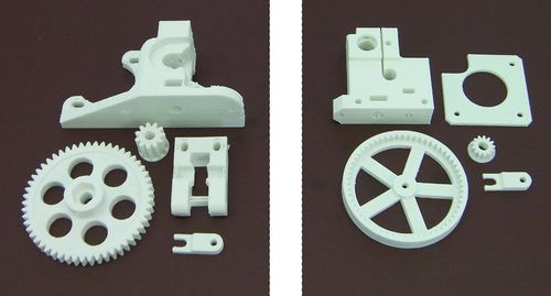
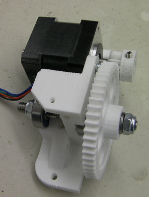
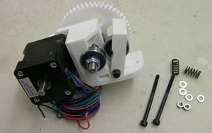
对于RepRapPro Mendel现在又两种可用的挤出装置,对于这两种所需的零部件分别呈现在左上图和右上图。T
如果你有的零部件是如左侧上图所示,那么你的组装指导救灾这里。
如果你有的零部件如上右图所示, 那么请点击这里.
目标
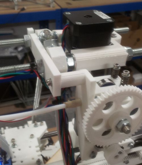
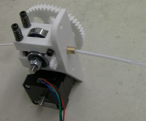
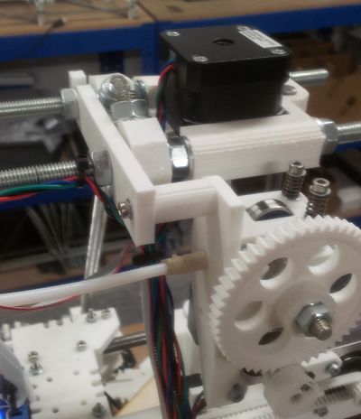
在这个阶段的最后,你的挤出机将会被安装在Mendel的背部,如下图:
但是没有图中的线。
第一步:电机和滚齿螺柱安装
| RP parts | Quantity | 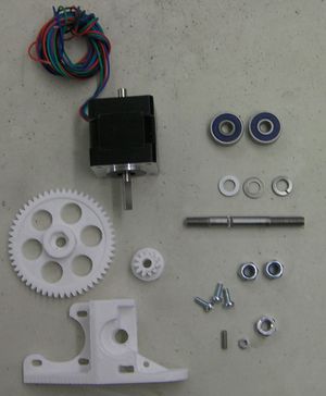
|
| 1 | ||

|
1 | |

|
1 | |
| Hardware | Quantity | |
| M6 滚齿螺柱 | 1 | |
| M6 螺母 | 1 | |
| M6 尼龙自锁螺母 | 2 | |
| M6 开口垫圈 | 1 | |
| M6 平垫圈 | 2 | |
| 626 轴承 | 2 | |
| NEMA 14 步进电机 | 1 | |
| M3x10mm 紧定螺钉 | 1 | |
| M3 螺母 | 1 | |
| M3x8mm 螺丝 | 3 | |
| M3x25mm 沉头螺钉 | 1 (Mendel中需要,Huxley中不需要) |
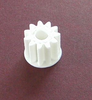
对于小齿轮的设计有两种,列表中所指的是需要平头螺钉的那种。
上图的齿轮是不需要螺钉的,只需对准电机轴将其轻轻敲打至适当位置即可。
如果你在组建一个Mendel,使用沉头螺钉穿过安装箱的洞(在打印块的倾斜区域),电机将会从这开始移动(头朝电机)。Huxley不需要这个螺钉,在你安装电机之后,你不用固定螺丝。
使用8毫米M3螺丝把电机安装在打印块上。尽量让它原理重心,放置它进入插槽。不要旋得太紧。电机的导线从底部出来,如下图所示:
把M6螺母(普通的,不是自锁螺母)放入大齿轮的六角凹槽中。
在螺柱上放上轴承(注意长短螺纹的相对位置),跟随者两个普通的M6垫圈,再试齿轮和螺母。螺母必须远离轴承。
你将要调节一些东西,所以齿轮啮合。
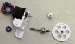
把M3螺母放入小齿轮的插槽中,旋紧M3固定螺丝。小齿轮可能需要用手扩孔,大概5毫米左右。一些电机的电机轴上有平坦的部分,如果你的也是这样,在电机轴上装上小齿轮,中心对着电机。然后把轴承放在它的凹槽,这样大齿轮和小齿轮啮合。为了阻止这样的情况,先放上轴承和大齿轮,然后再放上小齿轮(如下图所示)。
如果你有的是不需要螺钉的小齿轮,那么将其对准电机轴轻轻敲打至适当位置。
把事物分离,然后再一次组装它们,调节电机在凹槽中的的位置,直到齿轮可以很好的啮合。
当你开心的旋紧所有电机的螺丝时,重新安装所有的,然后旋紧小齿轮的固定螺丝。确保小齿轮的中心没有和大齿轮发生摩擦,它们之间应该有半毫米的空隙。
把另一个轴承放在打印块的另一端。
将开口垫圈装在大齿轮的另一端使得其固定齿轮螺母,然后在两端分别放上M6尼龙自锁螺母。
旋紧尼龙自锁螺母,检查滚齿对着2毫米洞,穿过打印块,这里将是碎屑进入的地方。滚齿应该放在这个中心。撤销或者拿起大齿轮和它的螺母,两个尼龙自锁螺母仍旧如此。
尼龙自锁螺母不要旋得太紧,太紧的话齿轮, 螺柱,电机不能自由的旋转。
Step 2: Idler
| RP parts | Quantity | 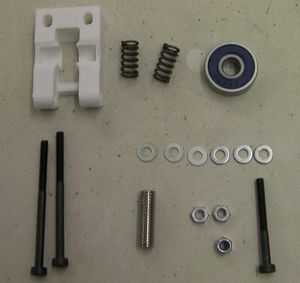
|

|
1 | |
| Hardware | Quantity | |
| M3x30mm screw | 1 | |
| 626 bearing | 1 | |
| M3x45 screws | 2 | |
| M6x20mm socket set screw | 1 | |
| M3 washers | 6 | |
| M3 full nuts | 2 | |
| M3 nylock nut | 1 | |
| Springs | 2 |
Put the bearing on the M6 set screw and drop it into the slot on the printed part. Check that it rotates freely. If it does not, use a blade to remove a little material where it is binding.
Fit the idler to the drive with the 30mm M3 screw, two washers - one each side - and the nylock nut. Don't over-tighten it - it must move freely. The photo below is wrong - you want the head of the screw on the gear side and the nut facing you in the picture. You will find that if you rotate the gear you can get the screw through the holes in it. This makes the idler much easier to remove when it is mounted on the RepRap machine.
Put the springs on the long screws. Sandwich each spring between a pair of washers.
Put the screws through as shown. If you drop the nuts into their holes with tweezers first, then hold a screwdriver blade over them while you tighten the screws this is less fiddly.
Step 3: The Bowden tube
| RP parts | Quantity | 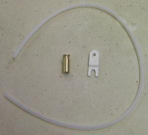 Don't confuse the PTFE tube (shown) with the shorter translucent heatshrink also supplied with the kit. |
|
1 | |
| Hardware | Quantity | |
| slotted brass retainer | 1 | |
| PTFE tube | 1 |
Use a sharp blade to trim a few millimetres off the end of the tube at right angles to get a clean square end.
If your kit has a 4mm diameter PTFE tube supplied (as opposed to 3mm) then make a small cone on the end with a pencil sharpener. Don't cut too far - PTFE is very soft. The cone makes it easier to start the thread.
Screw the tube into the brass retainer. Look in the other end (a magnifying glass is useful) to see when it gets to the end of the internal thread, then stop.
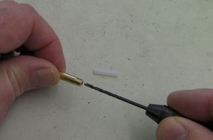
Screwing the tube in will have reduced its internal diameter slightly. Gently twist a 2mm drill by hand in the end of the brass to thin the tube where it is inside the screw thread. If you have a small hand-chuck this is made easier. The picture shows this being done for the other brass connector that you will install on the next page. The method is the same:
Push a short length of 1.75mm build filament down the tube from its free end to clear out any PTFE swarf.
Push the brass retainer into the drive, and secure it with the printed tongue. The thin end of the tongue goes to the right in this picture:
Note: the bowden start fitting (brass retainer) must be held centrally in the hole. If the fitting diameter is quite a bit smaller than the hole in the extruder drive block, wrap a couple of turns of masking (or similar) tape around the fitting before pushing it in.
Feed in the short length of 1.75mm filament. The compression screws should be done up just tight enough that when the filament is trapped in the drive you cannot pull it out by hand - no tighter. (Hold the big gear still when you tug to test this.) Turn the device by hand. The filament should feed slowly and smoothly down the tube.
Step 4: Fitting the drive
| |
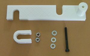
| Item | Quantity |
| Printed drive bracket | 1 |
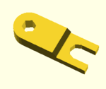
| Printed U clip | 1 |
| M3 washers | 3 |
| M3 nuts | 2 |
| M3 x 35mm screw | 1 |
Attach the drive bracket to the machine using the nuts on the top bars. It goes on the left of the machine viewed from the front, with the support cylinder at the back.
This view is from the back of the machine.
Use the screw a nut and two washers to attach the drive to the bracket.
Fit the U clip on the frame to match up with the countersunk screw that you fitted to the drive before fitting the motor.
Use a nut and washer to attach the drive to the clip. You will probably find that you have to hold the free end of the screw with long-nosed pliers to tighten the nut - its head is inaccessible, of course.
Finally, use the long-nosed pliers gently to remove the tongue. Take out the PTFE tube and its brass fitting. You will need these separate for the next step...
