DrillandFile Hot End
Release status: Working

| Description | A simple DIY hotend which can be made with only a drill press and hand tools
|
| License | |
| Author | |
| Contributors | |
| Based-on | |
| Categories | |
| CAD Models | |
| External Link |
Making your own hotend is like baking your own bread - there might be professionals out there who can bake better and have superior gadgets to do so, but nothing compares to your own, self-made bread.
This hotend is just another attempt at designing a simple hotend which can be made DIY-style without the need for expensive tools, machinery and materials. It was inspired by the Watson_Hot_End, the KISS_Hot_End and the Wildseyed_Simple_Hot_End.
The basic idea is to drill first, then file in shape. That is, you take a rectangular block of aluminium alloy, drill the holes for the ptfe sleeve and the nozzle first, and then start filing the block into its final shape. That way, the drilling precision that can be reached with a simple drill press is not critical, you can more or less drill slightly off-center and still end up with a very precise hotend after filing.
The heater block is drill/saw/file, the bracket is drill/saw and the insulator is drill/cut only. There is no lathe or milling required, neither for the heater block nor for the insulator. The M4 thread in the heater block (for attaching to the bracket) can easily be tapered by hand.
The materials are cheap, a single hotend costs probably no more than 5 EUR as far as material is concerned. However, to source the material, you probably need to buy slightly larger quantities (for example, you cannot buy a 20x35x12mm piece of aluminum alloy, you need to buy 20cm of 20x35mm bar at ebay for approx. 5 EUR - which you can use to build more than 15 heater blocks). I have bought material for approx. 30-40 EUR and now have enough in stock to build at least 10 hotends, that is, 6 more to go.
Summary:
- electric tools required: drill press
- common hand tools required: saw, file(s), drill bits 5mm, 3.2mm, 2mm, M4 inside tap
- special hand tools required: hand chuck and 0.5mm or 0.3mm drill bits for nozzle
- materials required: aluminium bar 20x35mm for heater, PTFE round material 5mm and 15mm OD for insulator, 3mmx20mm steel bar for bracket
- vitamins required: 2 power resistors 6.8R, thermistor, high-temperature silicon caulk
- skills: drill, file and tap an M4 thread
Contents
Status
The current version is v3 and works quite well. Besides printing calibration pieces and robotics parts, I have used it to print all parts for my Mendel90.
Here are some examples of prints made with v2 and v3 with a 0.5mm nozzle:
robot parts and a mendel90 x idler
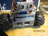
a small 3-wheeled robot
extruder bottom view (Gregs wade reloaded by jonaskuehling, http://www.thingiverse.com/thing:18379
extruder top view (Gregs wade reloaded by jonaskuehling, http://www.thingiverse.com/thing:18379


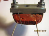
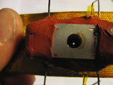
A view of the disassembled hotend with 0.5mm nozzle bore after initial use. Note, that there are no signs of leakage of molten filament. No filament is pushed back through the nozzle bore. The insulator sleeve and insulator main body shoulder seal the nozzle.

Component Overview and Functional Description


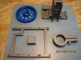
the main components are:
- heater block
- bracket
- insulator
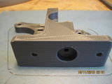
Heater Block
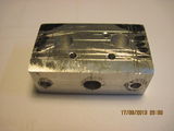
The heater block is made from aluminum alloy. It has a central bore of 5mm for housing the PTFE insulator sleeve. The central bore goes almost through to the nozzle end (minus 1.5mm). The nozzle bore (0.5mm or 0.3mm for example) is made using a hand chuck and a drill bit from the other side, so it aligns with the nozzle bore. Additionally, there are two 5mm bores for the wire-wound heating resistors and a single bore of approx. 2mm for the thermistor. At the top of the heater block there are two M4-threaded 3.2mm bores for the fixing screws.
Note that the heater block has no thread or other fixing means for the insulator. The insulator sleeve will push-fit into the central bore with the bracket pulling the heater block against the main body of the insulator.
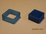
Also, despite its complex shape, the heater block is made from a single rectangular 20x35x12mm piece of aluminium alloy by simply drilling, cutting and filing.

Bracket
The bracket is made of ordinary steel (Baustahl) 3mm thick by 30 mm wide. Is has two bores for the fixing screws of the heater block and two bores for the M4 rods for fixing the whole hotend to the extruder (standard distance of 50mm for fixing to extruder). In the center, there is a cutout for allowing the insulator to pass through into the heater.

Insulator
The insulator consists of two parts: an inner sleeve of PTFE with an OD of 5mm and a bore of 3mm for the filament, and a main insulator body with an OD of 15mm, which has a bore of 5mm for receiving the sleeve. The inner sleeve is approx. 18mm longer and engages with the heater block. Because of this two-part design, the insulator assembly can be made without a lathe. All that is required are two rods of PTFE round material of 5mm and 15mm OD, respectively. See the build description for an explanation on how to make a centered 3mm bore into a 5mm PTFE rod using a drill press.

The inner sleeve is inserted into the central bore of the heater block and goes all the way through to the nozzle. I got this idea from the Watson_Hot_End v0.3, where there is also a long part of the PTFE insulator engaging with the nozzle.
The lower end of the inner sleeve is pressed against the end of the 5mm bore in the heater block. The long way of the inner sleeve seems to ensure that the filament is sufficiently heated when arriving at the end of the sleeve and entering the last 2mm through the nozzle bore. The pressure comes from the bracket pulling the heater block up against the extruder, with the insulator in between. That way, there is only compression acting on the PTFE insulator, no tension or shearing.
Additionally, the 15mm main body of PTFE is pressed against the top of the heater block, thereby sealing the central bore. I have only once experienced leakage of molten filament at the top of the heater block, after I had not tightened the brackets on the rods enough. When the rods are tightened properly, there is no back leakage.
As can be seen in the picture above, the push fit design has the additional advantage of being able to swap the heater block (e.g. for using a heater block with a different nozzle diameter) of the hot end without having to heat the hot end. Because the contact of the filament with the nozzle is only minimal at the end of the PTFE inner sleeve, the heater block with the mounted bracket can be easily pulled off after the nuts on the rods have been loosened, while the insulator with the cold filament remains in place.
Note: The insulator is cooled by a 40mm fan running at 12V (full speed) at all times (when the printer is powered). The fan is arranged perpendicular to the insulator so the air flow can cool the main insulator body constantly. I haven't measured it, but the insulator main body stays almost cool to the touch in the upper part, ensuring that no heat is transported into the extruder body via the insulator. Additionally, the M4 steel rods on both sides are cooled slightly as well.

v3 Build Description
The heater block is made from a block of 20mmx35mm aluminium. I have bought a 182mm long bar of Al Cu Mg Pb as a surplus piece off ebay for 2.60 EUR. This aluminium alloy is excellent for drilling, milling etc. and far superior to the aluminium you can get at your local home improvement store.
The drawing contains all the required measurements:

The bracket is made from a strip of steel, 3mm thick, 30mm wide. I have choosen steel because it is thermally at least a little bit isolating (in comparision to, for example, aluminium). The drawing contains all the required measurements.
Here is the build process in pictures (click on them to view them bigger):
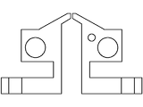
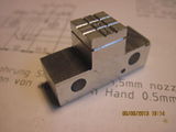
heater block side view for orientation, showing the arrangement of the central 5mm bore meeting the 0.3 or 0.5mm nozzle bore at the nozzle.
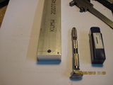
Take a 20x35mm alumium alloy bar, file the end flat and mark off 12mm. Then mark the positions of the nozzle bore and central bore on opposite sides (try to keep them aligned using a square ruler). Drill the central bore using a 5mm drill bit in the drill press. Drill almost through, but leave 2mm at the bottom.
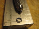
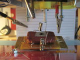
Flip the bar and drill the nozzle bore using a hand chuck and a drill bit matching your desired nozzle size. I used cheap 0.3mm and 0.5mm drill bits (2x10 pcs. for ~3 EUR, ebay) for this and they worked well. The drilling by hand through 2mm of aluminium takes only a few minutes. Take your time so the drill bit doesn't break.
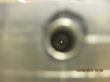
An inside view through the central bore showing the alignment with the nozzle bore (almost..)
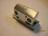
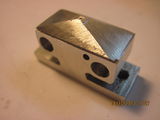
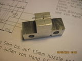
Cut off the 12mm hotend from the bar, file the sides flat and mark the bores for the thermistor, for the resistors and the cut lines for the final shape of the heater block. Drill the bores for the resistors and the thermistor using a drill press.
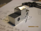
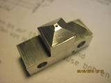
Here, all the cuts have been made and the M4 threads for the fixing bolts have been tapered. I use special hex bolts, but you can use ordinary M4 screws just as well.
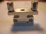
side view with the fixing bolts mounted
start shaping the nozzle filing at the long sides.
then shape the nozzle at the short sides.
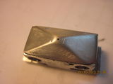
After filing the nozzle, I sanded it using 600 wet sand paper giving it a nice smooth finish
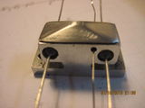
Insert the resistors (I use wire-wound 6.8R resistors from Reichelt) and the thermistor (I use the KTY 84-130) for a test. Before inserting them finally, I isolated the wires using Kapton tape.
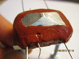
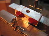
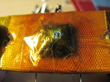
After inserting the resistors and the thermistor (wrap them with kapton tape to ensure a tight fit) I generously applied high temperature silicone caulk (I use red Wiko K80, which is rated for 300°C).
Top view with silicone applied. Admitted, with the silicone it doesn't look nice, but the silicone holds the resistors quite in place and also gives some thermal isolation.
Electrical connections are done by stripping the plastics off a terminal strip. The resistors are connected in parallel giving approx. 40 Watts at 12V. When mounted, I use alligator clips for the electrical connections of the resistors.
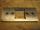
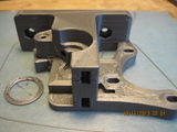
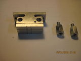
The bracket - a simple drill, cut and file job.
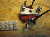
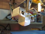
The heater block with electrical connections prepared and the bracket attached, ready for mounting.
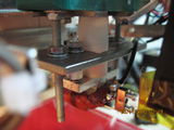
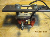
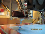
Finally, the hotend mounted on the printer. Mounting is done by simply pushing the 5mm PTFE sleeve into the central bore of the heater block and fixing the bracket on the M4 mounting rods. Make sure the top of the hot ends is fitted tightly against the insulator main body. The electrical connections in my setup are done using alligator clips.


Notes on Making the PTFE insulator
This hotend uses an PTFE insulator only, there is no PEEK required. This is made possible by the fact, that the insulator is only succepted to compressive forces and not stressed with tension or torsion.
I have made the insulator from two pieces of PTFE rod
- 15mm OD PTFE rod for the main body
- 5mm OD PTFE rod for the inner sleeve
Build instructions (unfortunately I have not made any pictures of this, so I will attempt a text-only description):
- cut the 15mm rod to length 40mm and file the ends flat
- using the drill press, drill a concentric 5mm hole into the rod (this is the most tricky part)
- cut the 5mm rod to length 60mm.
- next, we need to drill a 3mm hole for the filament into the 5mm rod. This is of course very tricky, but there is a technique for doing this quite easily. I learned this from a video of user wildseyed (http://www.youtube.com/watch?v=foR6teWZZG8):
- you use this technique at your own risk. we are only drilling relatively soft PTFE here, but still, be careful and don't hurt yourself.
- the basic idea is to insert the 5mm rod into the drill press and hold the 3mm drill bit with pliers instead
- start the drill press and carefully push the drill bit from below towards the end of the rotating rod
- the drill bit should center itself on the rotating rod and by pushing upwards you start drilling a centered 3mm bore into the 5mm rod
- you probably need to do this once from each end for drilling the whole 60mm length of the 5mm rod
- insert the 5mm rod into the 15mm rod. It should be longer by approx 20mm.
- insert the insulator assembly into the central bore of the heater block. The protruding end of the 5mm rod should be completely inserted into the heater block and the shoulder of 15mm rod should fit tight against the top of the heater block. You should feel how the 5mm rod touches against the end of the central bore in the heater block
- push the 15mm rod down against the heater block, then cut off any excess length of 5mm rod at the top end of the 15mm rod
The assembled insulator needs to be pushed into the mounting hole of the extruder. It might be necessary to cut off some of the 15mm diameter at the top of the insulator to make it fit into the extruder mounting hole. But I would advise against making the insulator smaller than 15mm diameter. (I have printed a custom extruder with a 15mm mounting hole).
Earlier Versions
v2 - Double heating resistors, bracket underneath
Version 2 used two heating resistors. The bracket was mounted underneath the heater block. There were no fixing screws for attaching the heater block to the bracket, the heater block was held in place by the bracket pressing upward from below.
This design has the disadvantage of a large contact area between the heater block and the bracket resulting in thermal losses into the bracket. At first, the hotend did not sustain the extruding temperature (PLA 185-190 °C) when in operation (feeding filament). Therefore, the bracket was isolated with some glass fiber fabric and wrapped with kapton tape.
After the isolation was in place, the hotend worked quite well. I have printed almost two 1kg spools of filament with the v2 hotend. (Before starting with the v3 hotend).

heater block with resistor bores, cutouts
cuts for filing the nozzle
nozzle filed (1)
nozzle filed (2)
hotend test intstall on printer
sealing the resistors and the thermistor with HT silocone caulk
the first filament extruded
calibration pieces
disassembly after the first print
the nozzle side (v3 will be much smoother and cleaner)
the top of the heater block, minor leakage traces


v1 - Single heating resistor, bracket underneath
v1 was the first design. It used a single heating resistor (5.6R 3W wire wound resistor) placed on one side of the heater block. The thermistor was placed on the opposite side. The bracket was mounted underneath the heater block for pushing the heater block upwards against the insulator. Both the thermistor and the resistor were cemented into the heater block with exhaust putty.
It kind of worked right away, I was able to heat it up to 185°C. However, it took a long time (probably more than 4-5 minutes). After it reached the target temperature, I was able to use manual extrusion mode to get some molten filament through the nozzle. However, doing so, the temperature dropped rapidly to 175°C. Therefore, this design was not fit for printing.
Still, there were some important lessons to be learned for the v2 design:
- more heating power needed (v2 will use two 6.8R in parallel, v1 only single 5.6R)
- the exhaust putty becomes brittle and breaks off easily (v2 will use silicone caulk)
- the thermistor needs to be closer to the resistor
Because of these lessons learned I would consider v1 useful.

