Heated Piezo for Jetting Wax
Release status: experimental

| Description | A Piezo design that can be heated for jetting wax.
|
| License | |
| Author | |
| Contributors | |
| Based-on | |
| Categories | |
| CAD Models | |
| External Link |
Contents
Introduction
I'm working on a Stainless Steel piezo that can be heated to jet colored wax. This is to be used as a "Mask" for printed circuit board fabrication. This process eliminates the need for applying and developing photo resist on a copper clad board. Instead, I use my 3-D printer as a 2-D printer where a board can be placed on my bed and printed directly from Eagle PCB layout software. Then the copper board can be etched and used.
This device can be used for SO many other things besides PC board fabrication. The wax might be able to make 3-D objects, but at the very least it can be used to label numbers and letters of your PLA, ABS, or Nylon parts. And an image could be applied to a surface of any 3-D printed device.
Overview
The basic system is a modified RepRap printer with a J Head Nozzle. The standard J Head nozzle has been removed, and a custom made heated piezo toolhead is installed in its place. The toolhead is made of several metal sheets sandwiched together. A flexible tube connects the toolhead to a reservoir containing molten wax. In operation, a driving circuit pulses the piezo disk mounted on the toolhead, resulting in deposition of molten wax droplets on the work surface.
There are three closed-loop controlled heaters in the system:
- a pencil cartridge heater on the toolhead
- a pencil cartridge heater on the reservoir
- a nichrome wire wrapped around the supply tube
Each heater receives temperature feedback from its own thermistor. The raw wax can be added to the bulk reservoir by dropping large pieces into the molten wax. One could have a system that melts wax into the bulk reservoir as needed. But since I'm focused on PC Board mask, I only need small amounts at a time.
Pictures
These photos show details of several different systems under test. Description of photos is below.
My Parts 0
My Parts 1
My Parts 2
My Parts 3
My Parts 5
Solid Ink Droplets 04-22-2013 A
Internal Chamber-02
A014 - 20130426 120558
A017 - 20130429 161406
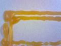
Image1
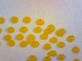
Image2
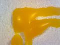
Image5
Piezo Testing 01


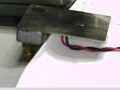
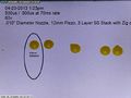
- My_Parts 0, 1, and 2 were when I was testing with colored water and no heat. So in these you can see how the portion of the heater block is needed for the fluidic fitting. In this version, the toolhead consists of 3 layers that are sandwiched together with a 20mm piezo on top. This design also works with a 12mm piezo and would most likely work with a 9mm piezo if the dimensions are adjusted slightly.
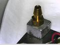
- Piezo_Testing 01 is another one where I was testing with no heat and colored water. But there is a fitting to measure pressure between the fluid reservoir and the basic piezo part.
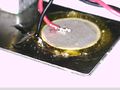
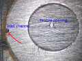
- Internal Chamber-02 shows where the ink comes into the chamber. This has the piezo removed and you can see how the piezo part completes the chamber. This part was later scaled down to a 12mm piezo and a smaller chamber.
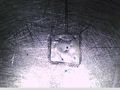
- The images of droplets on paper speak for themselves. The speed that the table travels relative to how fast the drops are ejected determines if there are individual drops or if there is a continuous stream to form a solid line.
Important Considerations
- The most important thing to remember is that the pressure of the fluid at the nozzle opening is critical. Too much pressure, (forward pressure) and the fluid will drool out of the front nozzle. Too much negative pressure, (back pressure) and the piezo cannot overcome the pressure and there will be no drops ejected. The sweet spot I've used is -2.0 inches of water at the nozzle, that is, the top level of fluid in the reservoir is 2.0 inches below the nozzle opening in the toolhead. This provides a visual meniscus from the outside of the nozzle.
- The second most important thing to remember is that the piezo goes through 2 important movements and both are extremely important. (Fine tuning these movements will make huge differences in the performance of the drops.) So with these movements, polarity is important. The first movement is away from the nozzle drawing in additional fluid and the opposite movement is toward the nozzle opening which should eject a small drop of fluid. These 2 movements combined create a sort of fluidic pump pulling in and ejecting the fluid on each cycle. So a complete cycle includes a voltage pulse in both directions. (+V, and -V means + movement and - movement.) So the bottom line is that the red wire goes to the outer plate of the piezo device I'm using and the black wire goes to the center conductor area.
- The fluidic path needs to be relatively small because of the pump action explained above. The movement that pulls fluid in uses a capillary action of the fluid to draw the fluid up and in. (By the way, this needs to be nothing but fluid. Bubble in this will ruin the whole process so a nice prime of the fluid when the device is first born is a good practice.) But it needs to be a small path because when the piezo goes through the opposite motion you want the fluid to be ejected out of the front of the nozzle and not back down into the fluidic inlet path. So I put an "S" curve in my design just before the chamber to allow for somewhat of a one way fluid path. Drawing fluid in can be a slower pulse and ejecting the fluid out can be a much faster pulse. (But these designs typically work with evenly sized + and - pulses of about 10us or larger.)
Details of Toolhead Construction
The toolhead is made of a stack of 3 or 4 metal plates. The stacked plates create a small path for the fluid, and a chamber where a small pocket of fluid will wait to be ejected. (Remember that heated wax is a fluid much like water or aqueous ink.) A drawing of the plates is available in this pdf file. The stack of plates needs to be attached to something that is large enough to put a heater cartridge in, and also provides a small reservoir for the fluid.
The Piezo Plates drawing shows the layers of the plates. Fluid flows down into and past (5) and past (3) and then travels along the channel in (2). There is an "S" curve in the channel in (2), just before the chamber, to allow for somewhat of a one way fluid path. When the fluid gets through the channel in (2) it has access to plate (3), which is the chamber where the fluid resides. The piezo is attached to (3) with 2 part epoxy. Plate (1) is the nozzle opening where the fluid will be ejected from the action of the piezo.
I ended up using a small pencil type cartridge heater. The C1E14-L12 is driven with AC pulses and is controlled by a separate micro-controller based on a thermistor which is attached to the outside of the heater plate (5). Note that the heater plate (5) has holes to accommodate a #10-32 fitting for the fluid intake as well as a 1/4-20 for the attachment to the 3-D printer barrel. I used the original PLA nozzle extruder as a mounting method using only the barrel as an interconnect.
I've used some generic sheets of double sided adhesive with great success. I've also used some solvent adhesives that are heat-cured at different temperatures. These solvent adhesive tend to get into the channels where you want your fluid to flow. So I've heated the plates, melted wax into the channels to mask them from the solvent and then pre-baked at a low enough temperature so as not to melt the wax but solidify the solvent adhesive. My most current design eliminated the pesky plates with a single piece machined part. In this design the piezo will be held in place with an O ring and a plate that can be removed for troubleshooting and failure analysis in cases where things don't work properly.

Electronics
WARNING
The electronics used in this project are potentially dangerous. Do not attempt to replicate this work unless you have the tools and qualifications to build circuits for mains electricity (120VAC).
Heater Control
The heater system has an external micro-controller that has closed loop control for 3 things. The 3 things are the large reservoir, the tube leading to the toolhead, and the toohead itself. Each of these runs on 120VAC and I have a circuit that is used to PWM each of these based on the thermistor for each one.
Piezo Control
The drawing shows the simple schematic that I've been using. I needed as much as 120volts in order to get things running. Once this system is optimized then I suppose that this could be as low as +50volts. Note that in my testing so far I've been using 2 external signal sources to drive each of the 1/2 circuits. This should be incorporated into the micro-controller at a later time when the +period and - period are better understood. These designs typically work with evenly sized + and - pulses of about 10us or larger.

Video
These are screen captures from video of the experimental results. Click on the link below each screencap in order to download or play the video in WMV format.
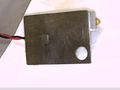
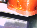
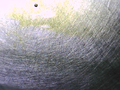
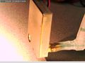
The still image of the Drops On Page video shows the pencil cartridge with the wires sticking out of it. The big red piece to the right is a heat jacket to keep the heat in. The off-axis reservoir has a heated pencil cartridge just like the one shown. The tube connecting these is heated with a nichrome wire around the length of the tube.
Video Link: Drops On Page
Drops On Page video: The jetting performance was poor but you can see that once I primed the system the drops started coming out again. This demonstrated that it can work on a 3-D platform. This performance is driving the need for local ink supply rather than off-axis.

Video Link: Drops On Transparency
Drops On Transparency video: I should have moved the transparency in a fixed pattern to show how the drops can stack on top of each other but I was too happy that the video was being collected that I didn't think about a better approach. This shows that a stream of drops can be sustained for a longer period of time. You may notice that a portion of the video clearly show a main drop and a shadow drop. This shadow drop can be optimized and eliminated with some small adjustments since this would clearly have adverse effects on a printed part.

Video Link: Drops After Print 01

Video Link: Drops After Print 02
Relevant Forum Threads
Related Wiki Pages
- Scratchbuilt Piezo Printhead For ideas on heads that are not heated
- Reprappable-inkjet A non-heated 3D printable piezo inkjet toolhead
- Waxuum A heated hollow needle tool for subtractive machining of wax