Melzi
|
English • العربية • български • català • čeština • Deutsch • Ελληνικά • español • فارسی • français • hrvatski • magyar • italiano • română • 日本語 • 한국어 • lietuvių • Nederlands • norsk • polski • português • русский • Türkçe • українська • 中文(中国大陆) • 中文(台灣) • עברית • azərbaycanca • |
Release status: working
| Description | Release Version 2.0
|
| License | unknown
|
| Author | |
| Contributors | |
| Based-on | |
| Categories | |
| CAD Models | |
| External Link |
Contents
- 1 Introduction
- 2 Versions
- 3 Source files
- 4 Setting up Melzi
- 5 Melzi additions
- 6 Melzi Fixes
- 7 Twin motor attachment on the Z axis
- 7.1 Mini-USB connector detached from board
- 7.2 Can't connect to the Melzi (FTDI driver problem)
- 7.3 Melted screw terminals
- 7.4 Hotbed or extruder reporting wrong values
- 7.5 The avrdude errors when flashing firmware
- 7.6 X axis only moves in one direction and/or Endstops do not work
- 7.7 Melzi Issues (Geeetech)
- 8 How to get it
Introduction
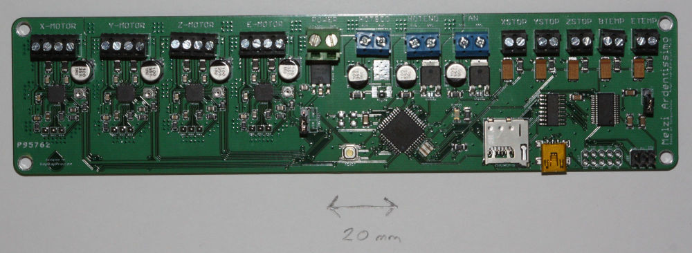
A compact all-in-one controller board for RepRaps with one extruder head, optimized for mass production.
The point of RepRap is to make itself, of course. But sometimes people just want plug-and-play RepRap electronics so they can concentrate on the other aspects of the machine, or just because they are more software or mechanics oriented than electronics oriented.
Melzi is designed to be a complete set of RepRap electronics that should be very cheap to mass produce. It was originally based on the Arduino Leonardo and is named after Francesco Melzi, who was Leonardo da Vinci's pupil.
Versions
Field guide to identifying your Melzi board:
| Board Name | ATMEGA mcu | Stepper Drivers | Manufacturer | Year |
|---|---|---|---|---|
| RepRap Melzi 2.0 | 1284P | A4982 | RepRapPro | 2012-present |
| "Melzi 2.0 1284P" (eBay hybrid) | 1284P | A4988 | Various eBay vendors | 2012-present |
| Melzi Ardentissimo 1.0 | 644P | A4988 | RepRapPro | 2011 |
Melzi Version 1.0 (Ardentissimo)
The Melzi V1 used a ATMEGA 644P microcontroller, and 4 x A4988 stepper drivers. However, problems with the routing of the fine tracks on the PCB quickly became apparent, which made them hard to make reliably. Often thermistor readings are inaccurate, or fail.
BEWARE! Some cheap online sellers still sell this version of the Melzi! See 'How to get it' list lower down this page.
Melzi 1.0/2.0 eBay Hybrid
Most listings online for "Melzi 2.0 1284P" or "Melzi V03" (as above) actually use the 1.0 board schematic, including "Melzi Ardentissimo" lettering and A4988 steppers like the 1.0, but use an ATMEGA 1284P microcontroller like the 2.0. Firmware for the 2.0 will work on these hybrids, however the ADC problems still exist. Some boards register a full 10C less than they should... but only when the printbed is activated, indicating severe EMF and/or power stability problems. As a general rule these boards should not be trusted.
Melzi Version 2.0
Specification:
- Processor: ATMEGA1284P (Sanguino compatible)
- All screw connectors - no soldering
- Micro SD card slot for GCode files
- Mini USB interface
- 4 x A4982 stepper drivers
- 3 x MOSFET drivers for hot end, bed and cooling fan
- Dimensions: 210mm x 50mm x 17mm
- Weight: 70g
Source files
Version 1.0 of Melzi was developed by Joe Mosfet.
Version 2.0 of Melzi was developed from Joe Mosfet's original by RepRapPro Ltd. It can be found at: https://github.com/reprappro/melzi
Setting up Melzi
Most boards are supplied with bootloader and firmware pre-installed and the stepper driver currents preset. If not, read on...
Bootloader Upload
If the ATMEGA chip on your board is supplied blank or you have had to replace the chip on your Melzi (for example, if you have short circuited the ATMEGA chip), you will need to flash/burn a bootloader onto the chip.
To replace the Atmel ATMEGA1284P chip on the Melzi, this is the technique RepRapPro uses:
- Remove old Atmel ATMEGA1284P chip - we find a hot air soldering iron is easiest; be careful not to overheat the crystal that is right next to the chip. You can heat it up in a solder oven, but be careful not to nudge other components.
- Solder on new chip - make sure it is the right way around! Use a flux pen to put plenty of flux on the board first, then solder the chip in place. You can do this with a fine tipped soldering iron, hot air soldering iron, or solder oven.
- Check there are not bridges on the pins with a strong magnifying glass or microscope
Uploading the bootloader with an AVR programmer:
- The chip comes blank; you will need to flash/burn a bootloader onto the chip. When it's blank, it can't even talk via USB, only via the In-Circuit Programming (ISP) pins on the board.
- To burn the bootloader, you will need an AVR programmer, like http://www.atmel.com/tools/AVRISPMKII.aspx This is the official one, and quite expensive, but cheaper ones are available on ebay. Check that you get one that is compatible with ATMEGA1284P chip; the USBtinyISP does NOT work with these chips.
- Download the latest version of Arduino IDE software (at time of writing 1.0.5) from http://arduino.cc/en/Main/Software
- Make sure you download the latest 'Sanguino' folder from https://github.com/reprappro/Marlin and put it in your Arduino/hardware folder (there should already be other folders called 'arduino' and 'tools' in this folder)
- Connect the AVR programmer to your PC, via USB. Connect the programmer to the Melzi, via the SPI pins. Connect USB to the Melzi - it needs power from the USB.
- Open Arduino IDE. Under 'Tools | Board' menu, select 'Sanguino W/ATmega1284p 16 mhz'. From the 'Tools | Serial Port' menu, select the port your AVR Programmer is on. From 'Tools | Programmer' select your AVR Programmer type.
- From 'Tools' menu, select 'Burn Bootloader'. You may receive an error; search the internet with the error message to troubleshoot what part isn't working properly. It mostly depends on the AVR Programmer you are using. Of course, there may also be a problem with your board.
Uploading the bootloader with an Arduino UNO as an In-Circuit-Programmer (ISP):
- You can burn/flash a bootloader with a Arduino UNO. The first thing is to turn your UNO into an ISP by programming it with the ISP software.
- Download the latest version of Arduino IDE software.
- Open Arduino IDE. Load the ISP software 'File | Examples | ArduinoISP'. Under 'Tools | Board' menu, select 'Arduino UNO'. Select the correct serial port.
- Click on the upload button to transform your Arduino UNO into an ISP programmer. Don't worry, your UNO doesn't have to be an ISP forever; it can be reprogrammed for other purposes at any time.
Once the Arduino UNO is an ISP programmer, one can connect it to the Melzi board with 4 wires:
 * pin 1 MISO (Melzi) on pin 12 (Arduino)
 * pin 3 SCk  (Melzi) on pin 13 (Arduino)
 * pin 5 Reset(Melzi) on pin 10 (Arduino)
 * pin 4 MOSI (Melzi) on pin 11 (Arduino)
- Connect both Arduino UNO and Melzi board to your PC.(The Melzi board needs power)
- Download the latest 'Sanguino' folder and install it as described above.
- Open Arduino IDE. Under 'Tools | Board' menu, select your card from the Sanguinos listed. If you don't know the card, you can pick one randomly. If you have selected the wrong card, the Arduino UNO will not burn the bootloader and will give you an error.
- From the 'Tools | Serial Port' menu, select the port your Arduino UNO is on. From 'Tools | Programmer' select 'Arduino as ISP'
- If the board you selected previously wasn't the correct board, you will receive an error message saying something like board id 'XX' isn't the right one, where XX is in hexadecimal. If 'XX' is 'ff', double check wires, otherwise try another board type under 'Tools | Board' menu or check on Google the board type with the 'XX' value.
Firmware Upload
There is a version of the Marlin RepRap firmware for Melzi on RepRapPro Ltd's Github repository here. It contains the extra files needed for the Arduino IDE to talk to a Sanguino (and hence to the Melzi). These also allow you to flash the bootloader using an appropriate programmer.
There are more detailed firmware instructions on the RepRapPro site here.
As an alternative to the Marlin firmware there's the Repetier firmware for the Melzi which in my case worked better than the Marlin firmware. More details about this firmware can be found here. There's also a special firmware configuration tool (v0.92) with some nice features. If you like Repetier you can donate some money.
Melzi Arduino Pin Numbers
#define X_STEP_PIN         15
#define X_DIR_PIN          21
#define X_MIN_PIN          18

#define Y_STEP_PIN         22
#define Y_DIR_PIN          23
#define Y_MIN_PIN          19

#define Z_STEP_PIN         3
#define Z_DIR_PIN          2
#define Z_MIN_PIN          20

#define E0_STEP_PIN         1
#define E0_DIR_PIN          0

#define LED_PIN            27

#define FAN_PIN            4

#define HEATER_0_PIN       13 // extruder

#define HEATER_BED_PIN     10 // bed (change to 12 for breakout pin on header)
#define X_ENABLE_PIN       14
#define Y_ENABLE_PIN       14
#define Z_ENABLE_PIN       26
#define E0_ENABLE_PIN      14

#define TEMP_0_PIN          7   // Analogue pin
#define TEMP_BED_PIN        6   // Analogue pin
#define SDSS               31

#define SLAVE_CLOCK	   16
Setting motor currents
This is covered on this page: RepRapPro_Setting_Motor_Currents
Melzi additions
Melzi with Bluetooth
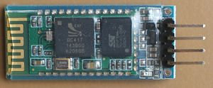
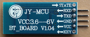
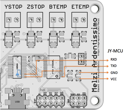
In order to get rid of the USB connection between Melzi and the PC one may like to use Bluetooth. There is a cheap module available in the market called 'JY-MCU' (vendor Shenzhen Jiayuan Electronic Co.,Ltd.).
Change setting
Before the module can be used the baud rate must be changed from default to 115.2k. Connect the module to a PC using a USB<->RS232 (RxD/TxD) interface with default settings (9600, N, 8, 1). The module shouldn't be paired at that moment. Use a terminal program and issue the following AT commands:
AT OK
AT+BAUD8 OK115200BAUD (set baud rate for Melzi)
AT+NAMEHUXLEY OKsetname (optional set name, default: linvor)
AT+PIN0000 OKsetPIN  (optional set pin, default: 1234)
More details about the configuration you will find here [[1]]
Wiring
We must level-shift the logic from 5V to 3.3V to communicate with the Bluetooth module. The Melzi has an 4050D IC with unused buffers that we can use. A total of 5 wires must be soldered. Note that the TXD outputs are connected in parallel which is not recommended. On Arduino boards the serial chip is connected to the main IC via 1kOhm resistors for this reason. These are not present in the Melzi board design.
Connect via Bluetooth
Once you have setup your BT devices you can select from drop down list and control your RepRap as usual.
Lcd screen
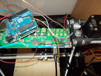
Gert added an LCD+rotary encoder on his Melzi, here are some pictures
A regular text-based LCD can be connected via I2C, as shown on this blog. The latest version of Marlin already supports a number of I/O expanders (PCA8574, PCF8574, MCP23017, MCP23008).
The Panelolu2 LCD+encoder is designed to work with Melzi and has an adapter board for easy connection.
Melzi Fixes
Broke your Melzi? Maybe you can find a fix here (feel free to add your fixes):
Twin motor attachment on the Z axis
Howto to be determined --Jobo (talk) 14:58, 6 September 2017 (PDT)
Mini-USB connector detached from board
A repair by Kevin T: http://forums.reprap.org/read.php?4,239276
Can't connect to the Melzi (FTDI driver problem)
There has been an issue where a FTDI driver update, pushed out through Microsoft update, disables Melzi controllers that have a non-genuine FTDI chip. This chip is used for USB communication, so the board may look like it's working (LED flashing) but doesn't show up correctly, and Arduino IDE/Pronterface can't connect to it.
This thread describes the problem in detail: http://hackaday.com/2014/10/24/ftdi-screws-up-backs-down/
Apparently, the only way to visually check the chip is described here: http://hackaday.com/2014/10/24/ftdi-screws-up-backs-down/#comment-2059852
There is a thread about it on the reprap forums here: http://forums.reprap.org/read.php?1,417199
There is a work-around for the problem (forcing driver installation, for Windows) here: http://forums.reprap.org/read.php?1,417199,418768#msg-418768
If the chip has been effected by the driver (ie deemed fake), the device PID is set to '0000'. You can check this in the Mac System Profiler, or on Ubuntu open a terminal window, run "lsusb" and it should show a device at "0403:0000". If you use Ubuntu, there is a tool for resetting the device PID correctly: http://www.minipwner.com/index.php/unbrickftdi000 Then update the FTDI drivers on your machines so it doesn't rebrick the FTDI chip.
Melted screw terminals
Sometimes, the screw terminals on a Melzi melt. More often than not, it's the bed terminal, and is due to the wire being poorly connected, ie loose in the screw terminal. It can also cause the MOSFET to fail, as it cannot dissipate heat generated as it switches on and off. RepRapPro advises customers to check the screw terminal connections periodically: https://reprappro.com/documentation/mendel-tricolour/maintenance/#Regular_maintenance
If the Melzi PCB is undamaged, you can simply replace the screw terminal. There are a couple of different screw terminal blocks, these are the most common:
This is the most common one - http://uk.farnell.com/multicomp/mc000048/terminal-block-pcb-5-08mm-2way/dp/2008019
this one is a bit taller, and easier to get the wires into - http://uk.farnell.com/phoenix-contact/mkdsn2-5-2-5-08/header-pcb-screw-5-08mm-2way/dp/1792766
The heated bed power cable carries about 10A at 12V, so any poor connection will tend to heat up. Check that your power and heated bed wires are stripped back far enough to go well into the screw terminals, and it's always worth checking that the screw terminals are well-tightened occasionally. Also, wire the printer with enough slack on the heated bed power wire so that it can be attached to frame, and there shouldn't be any movement of it at the Melzi end. But strain relief on any moving wire is necessary - try to make the movement in the actual wire, rather than at a connection point, to avoid the wire fatiguing.
Hotbed or extruder reporting wrong values
If your hotbed or extruder are reporting values even when the thermistor is not connected, it may be because the capacitor is spoilt. Try removing the capacitor and replacing it.
See RepRapPro Mendel/Huxley troubleshooting documentation for other temperature issues HERE
The avrdude errors when flashing firmware
The avrdude response is "avrdude: stk500_program_enable(): protocol error, expect=0x14, resp=0x50...)" when I try to flash firmware
First check that a new serial port appears when you plug the card into your PC. Then be sure that the microcontroller has been programmed with a bootloader (see 'Bootloader Upload' section).
X axis only moves in one direction and/or Endstops do not work
This may be due to bad 644P Fuse Settings. The settings come from the bootloaders "hardware/arduino/boards.txt" file from sanguino. Good setting for 644P board are:
 atmega644.bootloader.low_fuses=0xFF
 atmega644.bootloader.high_fuses=0xDC
 atmega644.bootloader.extended_fuses=0xFD
Then you need the reburn the bootloader with these settings.
Melzi Issues (Geeetech)
Below is a list of issues encountered with the Geeetech Melzi boards. These boards currently retail for as low as $50 USD (The v2.0 from other manufactures and some Sanguinololu's cost upwards of $80-90). My personal opinion is that the Geeetech boards are inferior, and will cost more in rework/repair/time than if a more expensive controller board were purchased instead (e.g. Melzi 2.0, Sanguinololo, or RAMPS). I purchased 5 of these back in January 2014, have repaired/reworked all of them, and have already replaced/upgraded two with other controllers --FlyingLotus1983 (talk) 19:47, 23 March 2014 (PDT)
- Random short-circuits on the PCB traces. This is a manufacturing defect that happens to cheap boards that are not electrically tested. For example, one board had a short between the X direction logic signal and ground, which caused the X axis to only move in one direction. Another board had one of the microstepping jumper signal wires shorted to ground, so when I set the jumper (MS1-3), this shorted out the 5V rail to ground, which is very bad and dangerous.
- The BTEMP and ETEMP resistors (R4 and R5) are the wrong value. The original Melzi was also 10K but changed to 4.7K over two years ago (The Melzi 2.0's use the correct value), however Geeetech is still using the wrong value. This hurts the precision of the thermistor, therefore it is better for to rework and replace with 4.7K than use 10K and change the thermistor tables in the Marlin firmware.
- The voltage regulator is not capable of 24V input voltage. This is understandable if it was designed this way, but the board should still say somewhere in the documentation "only supports up to 18V input" or something like that. It doesn't. The "fix" for this is to set the jumper ("PWR-SEL") to USB, and also to possibly disable/remove the 7805 voltage regulator. Another fix would be to buy a 7805 that is actually capable of 24V input, from Digikey or another distributer.
- The MOSFET transistors used will literally let out magic blue smoke if used with a standard Mk2b PCB heated bed wired for 12V. With 12V input voltage, and the Mk2b bed wired for 24V, the bed does not get hot enough to be useful. And when wired for 24V and given 24V input voltage, it does work, but only if an external heatsink is added to the MOSFET. This is very dangerous, and at the very least, the specifications of voltage and current should be disclosed to the user so they can add appropriate external MOSFET or solid-state relay. Obviously, as mentioned before, there are no specs anywhere on what sort of current/power the heated bed circuit can handle. The Geeetech boards do not use the RFP30N06LE's like the original Melzi board spec'd out, so I am unsure of exactly how much current and power it is capable of. Please use caution when hooking up a heated bed to this board.
- One of the boards resets when the SD card is plugged in. Have not yet gotten around to trying to troubleshoot this one. (This is standard on all Melzi boards, and is because the SD socket shares the reset pin, I think. However, it may be because the SD socket runs on 3.3V, which it gets from the FTDI chip.)
- The LED is really dim. They should use around 390 ohm for R25 but for some reason they use 1K.
- The stepper motor trim pots used to set current (T1-T4) are not set to a low value from the factory. If they are not set to something reasonable (say 0.4V) before the stepper motors are plugged in and power applied, the board will get really hot and may be damaged. Instead the board should be powered up at 5V using USB and the voltages at the trim potentiometer wiper should be measured with a DMM, and tweaked until they read 0.4 volts. This should be done for all four trim pots, preferably before shipping to the customer. Since this step is not done, do not forget to do it. They do not come with instructions.
Please note that after contacting Geeetech, they have issued a product recall for a batch of boards (From 12/2013 to 03/2014). They have posted on their blog how to get the replacement components.
They say that "the main problems are the heatbed and extruder thermistors are using resistors that are 10kohms instead of 4.7Kohms. Secondly, The MOSFTEs for the heatbed used the 10N06 which can only take 10A current (now changed to the 35N06). For customers who are facing the Melzi boards issues, please contact GEEETECH service team via [email protected], and we will ship you the components for replacement free of charge."
This probably means installing them yourself, but its quite good.
Digikey replacement parts for Geeetech Melzi:
P4.7KECT-ND (4.7 OHM 1/4 Watt resistor)
IPD035N06L3 GCT-ND (MOSFET N-CH 60V 90A)
How to get it
RepRapPro - Melzi V2.0

