RepRapOneDarwinThermoplastExtruder
This page describes something which is no longer the most recent version. For the replacement version see: ThermoplastExtruder 2 0
Contents
- 1 The Thermoplast Extruder version 1.1
- 2 This design is obsolete. For the up-to-date version see here.
- 2.1 Table of contents
- 2.2 Introduction
- 2.3 Improvements and alternatives
- 2.4 What order do I do things?
- 2.5 Safety
- 2.6 Bill of Materials
- 2.7 Extruder Controller Boards
- 2.8 Non-rapid-prototyped mechanical parts
- 2.9 Exploded view
- 2.10 The gear assembly
- 2.11 The motor drive assembly
- 2.12 The polymer guide
- 2.13 Assembling the extruder
- 2.14 Testing
- 2.15 Filament feeds
- 2.16 History
The Thermoplast Extruder version 1.1
This design is obsolete. For the up-to-date version see here.
These pages should be merged such that both pages do not attempt to cover the duplicate topics.
Table of contents
Introduction
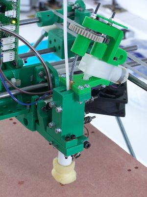
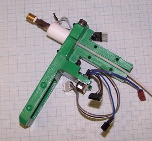
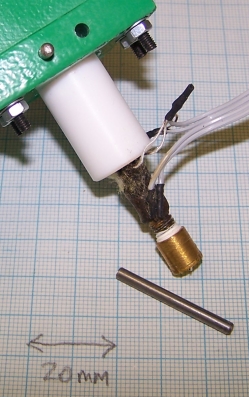
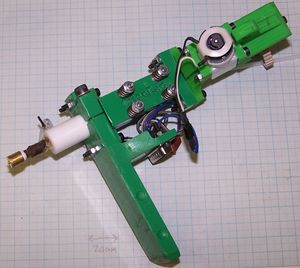
The thermoplast extruder is the central part of the RepRap machine. It takes a 3mm diameter filament of a polymer (usually polycaprolactone, polylactic acid, ABS or HDPE; the white rod coming into the picture from the top), forces it down a heated barrel, and then extrudes it as a melt out of a fine nozzle. The resulting thin stream is laid down in layers to form the parts that RepRap makes. The extruder should work with most thermoplastics up to a temperature of 200oC.
Improvements and alternatives
This page describes the standard RepRap polymer extruder. You may also care to check out the Extruder Improvements And Alternatives page for... well, improvements and alternatives.
What order do I do things?
Obviously you'll need all the parts and components first; the bill of materials is linked just there and below.
Start with the controller electronics, which you should have already made and tested if you have followed the order on the Main Construction Page. You'll need this to test and to use the finished extruder.
Next the mechanical parts need to be made.
Then make the motor drive assembly, then the polymer guide.
Finally assemble the entire machine and test it.
Safety
%RED%OBVIOUS WARNING: the heated nozzle gets very hot (almost as hot as a soldering iron). It is a bad idea to touch it or the wires leading to it when the machine is working or has just recently been switched off.
LESS OBVIOUS WARNING: The motor is geared down to drive the screw-thread very slowly. This means that, even though it is a fairly weedy motor, it is turned with a considerable torque. It is well-nigh impossible to get one's fingers in the works, but if one manages to do so, the motor will just keep going and injuries will occur.
WARNING FOR NON-CHEMISTS: The nozzle is partially made from PTFE. PTFE is stable up to 250 oC. Above that it breaks down into various gasses, some of which are quite toxic. The extruder should not be operated above 250 oC.%ENDCOLOR%
Bill of Materials
The bill of materials is on a separate page to allow you to flip quickly between it and this one. Open this link in a new browser window or tab to see it.
Extruder Controller Boards
These are part of the Generation2Electronics. You will need one DC Motor Driver and one PWM Driver.
Non-rapid-prototyped mechanical parts
The construction of the non-rapid-prototyped mechanical parts for the extruder is described on a separate page here. Make those next.
Exploded view
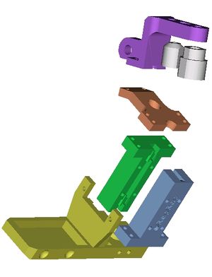
This picture shows all the rapid prototyped parts in an exploded view. The clamp is yellow. The screw-holder is green. The poly-holder (polymer filament holder) is blue. The motor-holder is red. The gear-bush-holder is purple. The motor-coupling (left) and drive-coupling (right) are both grey.
The gear assembly
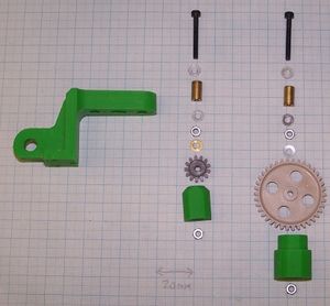
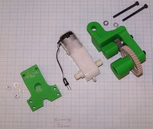
For this you will need the gear-bush-holder, the motor-coupling and the drive-coupling. You will also need two 20mm M3 cap screws, 6 M3 washers, 4 M3 nuts, the two bearings, and the gears. If you can get as large a washer as possible to go just under the brass bush for the larger gear. In the photograph all the washers are shown as the same size, but a big one will reduce wear in the gear-bush-holder, which can be subject to some thrust loading.
The picture shows the order of the parts as they go onto the screws.
The motor gear has a pitch circle diameter of 12 mm and the drive gear 36 mm. Any gears with these pitch measurements and 3mm central holes will will do. I used parts CDT0110 (outside diameter 15mm) and CDT0112 (outside diameter 40mm) from Greenweld.
Put a little silicone grease in the 6mm holes in the gear-bush-holder, insert the bushes, and clean excess grease away.
Put the screws through with washers on each side, and tighten up a nut against the bottom washer. The bush should rotate in the gear-bush-holder, not the screw in the bush. So do the nuts good and tight. The washers should prevent the bushes sliding out.
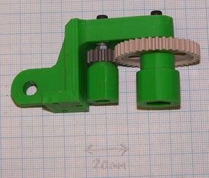
Then put the gears on with washers on the top but not the bottom (coupling) side.
Then fit the last two nuts inside the motor-coupling and the drive-coupling. There are hexagonal holes to accommodate them. You may find it easiest to put the nuts on a long screw, place them in the holes, then to unscrew the screw.
Screw the couplings onto their screws, doing them up tight (but not so tight that you damage the plastic of the couplings).
The mechanism should turn quite easily. If it is a little stiff, it should wear in. If it is very stiff, dismantle the assembly, run a 6mm drill down the bush holes to clean them out, then re-assemble it.
The motor drive assembly
Before you assemble the motor drive, you may want to lock the GM3 gearmotor clutch to provide more torque. This is not without risk: you get more torque, but if the drive stalls it may cause you to burn out the motor. With the gearing described above this should only be needed if you are dealing with very hard plastics.
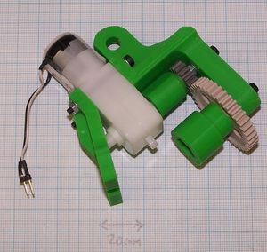
You'll need the gear assembly from above, the motor, and the motor-holder. Bolt these together as shown with two 35mm M3 cap screws.
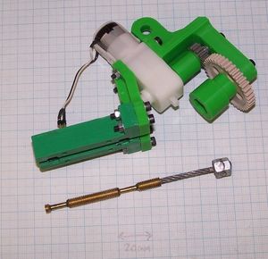
Then attach the screw-holder using four 20mm M3 cap screws.
Place the nuts of the she screw drive and flexible coupling in the hex drive attached to the gears. When you bend the flexible coupling the bearing lands on the screw should just sit comfortably in the half-bearing lands in the screw-holder.
Put a little lubricating grease on the half bearings. If you add too much, excess will get dragged down by the polymer you are using and mixed in the melt...
Finally, solder a 60mm length of fine two-way ribbon cable to the motor (insulate the terminals with heat shrink), and put a 2.54mm two-pin connector plug on the end.
The polymer guide
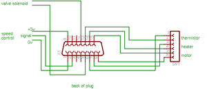
Start by wiring up the 15-pin D plug. Take a 70 mm length of 6-way ribbon cable and wire it to the right-hand end of the plug as shown - the diagram is looking into the back of the plug; that is the way you see it when you are soldering it. Use heat shrink to insulate the contacts with the plug. On the other end of the cable attach a 6-way 2.54mm pitch socket for the motor, heater and thermistor connections.
Optionally add a 2-way 2.54mm pitch socket on 70mm of ribbon for the valve solenoid, and a 3-way 2.54mm pitch socket on 160 mm of ribbon for the speed control. Neither of these are needed for the standard design, but they will be used for enhancements. It is probably easier to wire them in now rather than later.
Attach the D plug to the clamp using 10 mm cap screws.
Cut a 500mm length of the 3mm diameter polymer filament that you will be extruding. Push it into the barrel assembly in the hole in the PTFE rod.
Push the PTFE part of the extruder barrel into the hole for it in the clamp. Align it so that it is exactly flush with the top surface, and so that the wiring is at the front.
Clamp it lightly with the 25mm M5 cap screw, nut, and washer.
With a 3mm drill in a minidrill, hand drill, or small electric drill drill a hole through the PTFE using one of the two holes in the clamp as a guide. Push one of the 3mm pins into the hole you have drilled, then drill out the other one and pus a pin into that. Tighten the M5 screw in the clamp slightly more.
Loosely attach the polymer holder to the clamp using four 25mm M3 cap screws, four nuts and eight washers. Adjust the sideways position of the polymer holder in the slots in the clamp so that the polymer filament is centrally aligned with the channel in the polymer holder. Tighten the screws and nuts.
Assembling the extruder
For the final assembly you will need the four springs. The ones I used had an internal diameter of 5mm, a length of 12 mm, and a spring constant of 24 N/mm. They were Springmaster's & shuangyuan's compression spring D12100. But any spring of about that size will do. You will need to compress the springs to give a force of around 30 N each, so - as long as the spring constant will allow this and the internal diameter will fit over an M3 screw - you can use any compression springs you like. If you can't get springs, you can even use cut lengths of stiff silicone tube (such as that used to aerate aquariums), though these will creep, and so need to be tightened from time to time.
Insert the screw drive in the hexagonal hole in the drive gear coupling and push the free end against the bottom inside face of the polymer guide. Move the two together so that the screw-drive-bearing-lands sit in their half-round bearings. Holding the two together in your non-dominant hand, pick up a 50mm M3 cap screw and push it through one of the four holes in the polymer guide.
Put a washer on, then one of the springs, then a washer, then a nut finger tight.
Put the remaining three screws through next, and put springs on each, then finger-tight nuts.
If you can get them, use wing nuts rather than ordinary ones. This will make tightening and adjusting easier.
50mm is long for an M3 cap screw, and you may find them hard to obtain. You can replace them with four 55mm lengths of M3 studding. Put a lock-nut pair on one end to take the place of the screw cap, and you have an effective substitute.
The pitch of an M3 thread is 0.35mm. Tighten the (wing) nuts by as many turns will give about a 30N force in the springs. For the Springmaster's D12100s that means four turns.
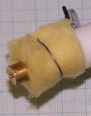
Finally, wrap a little fire-proof heat insulation round the nozzle. The glass-fibre wool that is used for building insulation is good (sneak into the attic with a pair of scissors when nobody's watching...). Secure it with a twist or two of bare wire. Solder works well.
Testing
Solder a 6-way ribbon cable long enough to reach the controller PCBs in your RepRap machine onto a 15-way D socket and connect the thermistor, heater and motor wire pairs to 2-way 2.54mm-pitch sockets. Connect these as shown on the single Arduino wiring diagram.
The heater and thermistor do not have any polarity and can be plugged in either way round. You are about to test if you have the motor connected the correct way.
The extruder can be tested on the bench with no actual RepRap machine present. All that is needed is an Arduino, the two driver PCBs, and a power supply. Follow the instructions here for programming a single Arduino controller.
Mount the extruder vertically in something that will hold it securely with the nozzle about 100 mm above the workbench; I use a chemistry-lab retort stand and clamp.
Connect a USB cable between your computer and the Arduino. Connect the power supply to the driver boards and turn it on.
Run the Reprap software, and select the extruder tab in the Bot Control Panel. It should look like this.
Don't worry if the numbers are different. In particular the reported temperature may not be all that close to room temperature, even though the extruder is turned off. The thermistor circuit is designed for accuracy at its operating temperature, not room temperature.
Set the motor speed to 170. While watching the larger driver gear, click on the "Extrude" button to turn the motor on, then immediately click it again to turn it off.
Did the gear try to turn anti-clockwise? That is, was the screw driving the polymer filament downwards? If not, turn the two-way motor plug round.
Set a low target temperature of 50oC, and click on the "Heat is off" button. The temperature should start to rise, though this will be slow.
When the tempearture is within a few degrees of the target, increase it by 20oC, and wait again. Repeat this until you get to the working temperature for the polymer you are using.
For polycaprolactone working temperature is about 140oC.
For polylactic acid working temperature is about 160oC.
For HDPE working temperature is about 170oC.
For ABS working temperature is about 190oC.
You may see polymer start to ooze from the nozzle as the extruder gets hot and it expands in the barrel.
When the extruder is at the working temperature give it two or three minutes to stabilise, then click on the "Extrude" button. If the motor doesn't turn, increase the "motor speed" value by 5 and try again. The extruder should work with values between 180 and 215. Much above the higher, and you will put some strain on the motor.
If you mark the filament above where it is fed into the top of the extruder you should be able to follow the mark you make against the rotating drive thread. Both should go at the same speed. If there is slippage, tighten the spring nuts. But do not over-tighten them - making them too tight can jam things up as well, with friction against the polymer guide.
Run the motor as slowly as it will reliably go at first. After a while polymer should start to extrude from the nozzle.
Congratulations! You have a working RepRap Thermoplast Extruder.
Filament feeds
As the filament is fed through the extruder, the screw drive causes it to rotate slowly. This has to be accommodated.
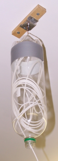
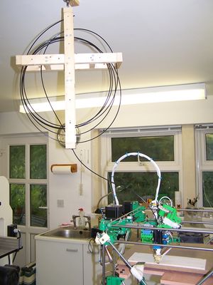
Start by attaching a rotating sky-hook to the left of your RepRap machine. The easiest way to do this is to put an old ball-race in a hole in a piece of wood, put a screw through the bearing's central hole, wrap stiff wire round it to make a hook, then clamp the lot together with a nut on the screw. Attach this to the ceiling.
The simplest feed for the softer (hence more flexible) polymers like polycaprolactone and HDPE is just an inverted two-liter drink bottle with string hung on the hook. Stuff the filament in, and it'll come back out in the reverse order of its insertion without tangling.
For the less flexible polymers like PLA and ABS, I made the cruciform wood spool shown on the right. I just wrap the filament round it. It is fed out through a hole in the piece of wood at the bottom.
History
The Darwin extruder is a variation of the RepRap Mk II Extruder designed by Adrian Bowyer from an original idea by Vik Olliver. See that link for details.
-- Main.AdrianBowyer - 06 May 2007
