SupportExtruder 1 0
Contents
- 1 The Paste Extruder Version 0.1
- 1.1 Version
- 1.2 Introduction
- 1.3 What order do I do things?
- 1.4 Safety
- 1.5 Bill of Materials
- 1.6 The solenoid and its connector
- 1.7 Assembly of the base clamp and valve mechanism
- 1.8 The nozzle and pipe assembly
- 1.9 The balloon/bottle mechanism
- 1.10 Final assembly
- 1.11 Testing
- 1.12 The machined balloon/bottle mechanism
The Paste Extruder Version 0.1
Version
This extruder is still under development, so its design will change. But it works and it can be built now.
Introduction
The RepRap paste extruder is designed to lay down pastes at room temperature. The typical consistency of the paste would be the same as icing sugar for cake decoration in a piping bag, or wall-crack filler such as Polycell Fine Surface Polyfilla, or silicone bath and shower sealant. Indeed all these and more have been successfully used with this device, though if icing sugar is left in it after use, it slowly dissolves to form syrup...
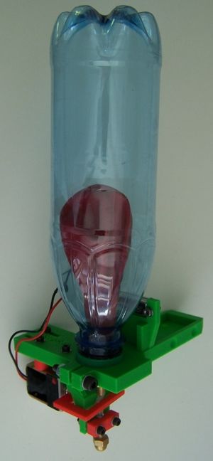
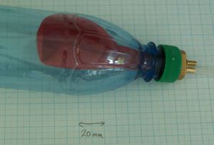
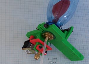
The paste is held inside a balloon (red in the picture) which is, in turn, held inside an empty fizzy drink bottle (transparent blue). The bottle is pressurised with air using a bicycle pump, and the pressure drives the paste out of the balloon, down a tube, and out of the brass nozzle at the bottom. A section of the tube is made from soft silicone, which is clamped by a latching solenoid. Closing and releasing the solenoid controls the flow.
It might be thought that, as the paste became exhausted, the air pressure would drop and so the flow would be uneven. But the volume of the balloon is typically 50 ml and the drink bottle typically 500 ml, so, by Boyle's Law, the pressure drop is only 10% or so - not sufficient to change the flow rate significantly.
What order do I do things?
First, obviously, you need to obtain all the parts which are listed on the Bill of Materials page.
Start by wiring up the solenoid.
Then use the nuts and bolts to put the rapid prototyped parts together.
Then put the bottle/balloon assembly together.
Then unite the two, plug it into your RepRap machine, and test it dry.
Finally, unplug it, charge it with paste (silicone bath sealant is a good reliable one to start with), and use it to lay down a design.
Safety
I can't think of any way that you might injure yourself with this device (unless you decide to use it to lay down nitroglycerine paste...). If you went crazy while pressurizing it, the drink bottle might split, but even that probably wouldn't do much harm.
Bill of Materials
Follow this link for the Paste Extruder Bill of Materials.
The solenoid and its connector
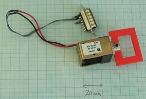
Start by soldering the solenoid to the 15-pin D-plug. The wires in the picture are probably a bit long (it is the prototype...). You should be able to manage with just the red and black wires from the solenoid itself. The red wire goes to Pin 15 and the black to Pin 8. Put heat-shrink sleeves on the wires before you solder them, then slide them down over the pins and shrink them on to insulate the joins.
Also solder a 10K resistor across pins 6 and 13. This has nothing to do with this extruder; it is a fake thermistor that keeps the extruder controller happy. The same controller is used for this extruder and the RepRap Thermoplast Extruder. When it's controlling that it keeps taking the temperature of the thermoplastic in an interrupt routine. This 10K resistor fools that routine into working...
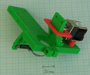
Attach the pipe clamp (the red rectangular piece) to the solenoid's core using a 15 mm M3 screw and nut - no need for washers.
Assembly of the base clamp and valve mechanism
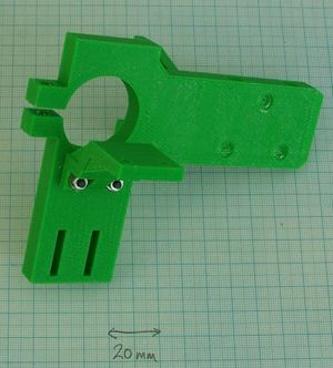
Attach the pipe holder to the base clamp on the opposite side to the D-connector holder and the RepRap logo. Use two 20 mm M3 screws, two M3 nuts and four washers.
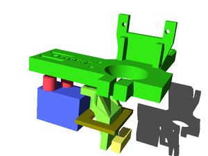
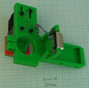
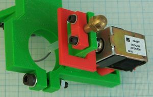
Next attach the solenoid with the rectangular hole in the pipe clamp going over the pipe holder. Use two 25 mm M3 screws with washers under their heads. These go through the adjusting slots, then through the two cylindrical solenoid spacers, and finally into the tapped holes in the solenoid body. The picture on the right shows a view of it fitted taken from underneath.
To get the position right, cut a 40 mm length of soft silicone tube and slide that between the pipe clamp and the pipe holder. Snap the solenoid to its latched position (that is, with its internal magnet holding the core as far up the central tube as possible). Then use your fingers to compress the pipe clamp against the silicone tube tight, sliding the M3 screws back in their slots. Now tighten those screws.
You should find that the latched solenoid holds the pipe clamped shut, but that when you force it open with a screwdriver the elasticity of the silicone tube is enough to keep it open.
Now use two 10 mm M3 screws and nuts to attach the D-connector to its holder. Put washers under the nuts. The connector goes at the back of the holder (furthest from the solenoid) with the broader part of the connector (pins 1 through 8) at the bottom (nearest the solenoid).
Put a 30mm M5 nut and bolt with two washers through the bottle clamp and do it up loosely.
The nozzle and pipe assembly
This is one of the parts the design of which will change. At the moment it uses the 40 mm length of silicone tube, two turned brass parts, and a standard RepRap nozzle. I hope to replace the turned parts with RP parts soon.
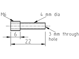
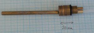
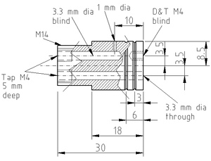
Until then, the drawings for the parts are below. The larger is a 4 mm tube with a short length of M6 thread at one end. A standard RepRap dome-nut nozzle but without the thermistor fits on that.
The smaller is a 4 mm tube with an M4 thread cut on one end. You will need two of these. If you use the resin cast valve mechanism (see below) make the threads cut on the ends M3, not M4.
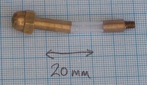
This shows the assembly fitted into the valve mechanism. The top end of the longer brass tube should just line up with the top of the clamp, leaving the length of silicone tube to be clamped by the solenoid.
The balloon/bottle mechanism
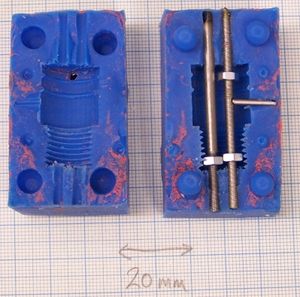
There is an alternative way to make this by machining described at the bottom of this page. The method described in this section takes a rapid-prototyped blank (in the file valve.aoi), then uses it to make a mould which you then use to cast a resin part.
There are general instructions on making moulds and casting on this page here. Read that thoroughly before starting this. Also look at the machining description below even if you're not going to do that. This will give you a clear idea of what it is you are making.
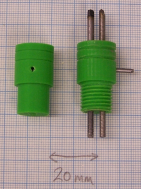
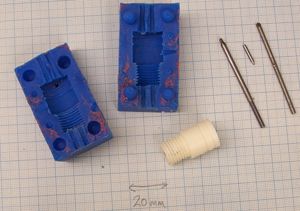
This shows two copies of the rapid-prototyped blank. On the left is how it comes out of the RP machine. You have to cut an M14 thread on it using a die (RP doesn't do good threads). You may also have to smooth off the outside of the larger cylinder by spinning the device in an electric drill and polishing it with a little fine emery paper - it needs to be smooth as the balloon will bear against it with a film of silicone grease in between and no air must leak under pressure.
You will also need some cores, which are shown inserted on the blank on the right. The left-hand one is a piece of 3mm rod with an M3 thread cut at the bottom end. The one to its right is a length of M3 studding (you could use this for the left-hand one too, if you like - it will work just as well). There is also a little one placed in the side air hole that is a smooth rod 2mm in diameter.
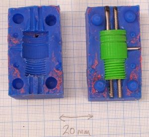
Using the techniques described on the mould-making page cast silicone round the blank in two stages to give a top and bottom half of the mould.
Removing the master pattern. Cover the cores with a thin film of silicone grease and replace them, putting M3 nuts on the threaded sections as shown. These nuts should be a couple of mm from the walls of the mould. They will set in the resin to give a strong thread to screw things into. If you file a small notch on the M3 studding core the 2mm diameter smooth one can fit in that; a small blob of grease will help it to stay put.
Put the halves of the mould together, holding them with elastic bands (not too tight - this will distort the mould). Pour in the resin and leave it to set.
This shows the finished device with the cores removed. The embedded nuts can't be seen, of course, but they will allow the easy attachment of the other parts.
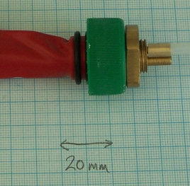
Before attaching the balloon, cut off the rolled rim that normally goes between your lips when you blow it up. If this is left on, the air can't get out from the one-way valve that the balloon makes by covering the air inlet hole. The two O rings holding the balloon make sure that the air does not blow up into the paste in the balloon, but instead goes into the bottle.
When assembling all these parts put a thin film of silicone grease on them. This both makes assembly easier and ensures that everything is air-tight. Just do everything up hand-tight; there's no need to use spanners and pliers.
Drill a 14 mm hole in the centre of the bottle cap, then use a thin M14 nut to secure the device as shown (this picture shows the machined valve device - the resin one would work exactly the same). If you can't get a 14mm drill, then 9/16" imperial size is very close (14.3mm) and will work fine.
You may have to roll the balloon round its support rod, excluding air from it, to get it through the neck of the bottle. Just do the bottle and its top up hand-tight again; that makes a gas-tight seal when the bottle is full of pop, so it's good enough...
Push the second small 4mm tube with the M3 thread into the end of the remaining silicone tube, leaving the thread exposed. Put silicone grease on the thread and screw it into the right-angled one-way-valve hole in the base of the M14 threaded brass.
Use a bicycle pump to put a few puffs of air down it to pressurise the bottle (don't overdo it). The balloon should collapse as the air in it is forced down the other tube.
Place the assembly under water and check for bubbles, implying leaks. Fix any you find with a little tightening (no too much) and maybe a little more grease.
Dry the bottle off with a paper towel.
Final assembly
Unscrew the air inflation tube from the bottle and put it to one side.
Slacken off the M5 clamping nut and put the bottle in its clamp. The M4 thread on the top of the valve tube should just touch the holes in the base of the M14 threaded brass. By rotating the bottle you should be able to screw its through-hole (marked) onto the top of the valve pipe. Put a little silicone grease on the M4 thread to make it paste-tight before you do.
Tighten the M5 bottle clamp with the connection to the valve at the rear (neared=st the RP valve-pipe support).
This should leave the air inflation hole at the front. The picture shows it with the inflation tube screwed in.
Testing
The machined balloon/bottle mechanism
This is a little complicated, though easy enough to turn on a lathe and drill with a drill press.
The straight-through tube is the one that the paste flows down from the balloon to the nozzle assembly just described.
The tube that turns a right angle is the air inlet. The skirt of the balloon covers this, forming a one-way valve that lets the air in but not out. The balloon is held on by two 15 mm internal diameter 2.5 mm thick O rings that sit in the grooves. A third O ring of 12 mm internal diameter and 2.5 mm thick goes at the top of the M14 thread and is trapped between the device and the bottle top.
Here is the drawing.
Mark the through-hole on the base (the M14 threaded end) with indelible marker.
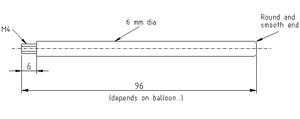
The blind M4-tapped hole is to retain the balloon support below. This makes sure that the balloon does not collapse over the outlet hole blocking it. If you use the resin valve mechanism described above, make the thread on the end of the rod M3, not M4. Also place a small greased O ring on the thread before screwing it into the valve to make a paste-tight seal.
