Quartz tube test will begin tonight, any test request?
Posted by ggherbaz
|
Re: Quartz tube test will begin tonight, any test request? November 06, 2014 10:45PM |
Registered: 10 years ago Posts: 1,401 |
I didn't draw the threads because it's just a basic design, but once we can come up with the final design I will generate a full stl file for production.
I know there is a lot of good guys here in the forum, some have already design their own hot ends and that is really valuable to me (Any expertise is truly appreciated)
One thing I need to clarify though, i'm not making this with any intentions on selling it or commercialized it. I just want to have a good reliable hot end that can print any material without issues, if after I built it it ends up been a good hot end, everyone will be able to download the files and built their own.
|
Re: Quartz tube test will begin tonight, any test request? November 06, 2014 11:06PM |
Registered: 10 years ago Posts: 1,401 |
so far, the three alternatives are:
Hot/cold seal: the only issue here is that quartz don't shrink or expand to much, so the main part will be heating the brass heater block. I don't know if by using this method the quartz tube can be stressed to much?
Glue seal: simple and cheap, but a pain if pipe brakes.
Press fit: like shown in my design, it's the simplest of the three, but maybe prone to leaks?
Someone mentioned using thicker pipe, I was thinking of this too, but I think thinner is better. My test showed that at 240, after 2 cycles of 30 minutes the top of the pipe never exceeded 83 degrees, with this temperature active cooling is not needed and I don't know if using thicker ones will work the same.
I think that the pipe needs to be anywhere from 30 to 40 mm long, the longer the better, but don't think anything under that will be sufficient. when I was extruding I could see the filament expanding up to 3/4 of the pipe. Unfortunately my experimentation was cut too short and several questions remain, so even though I was able to print about 2 1/2 hours and did it without cooling, more experimentation is needed in order to fine tune the hot end to get the best of it.
If I cannot find someone here that can help me with the manufacturing of the parts, I will have to deal with Aliexpress (cheapest so far) and get the parts made slowly at my budget pace....
Edited 1 time(s). Last edit at 11/06/2014 11:06PM by ggherbaz.
|
Re: Quartz tube test will begin tonight, any test request? November 07, 2014 05:54AM |
Admin Registered: 11 years ago Posts: 3,096 |
Hey, I love your new design, however, one tricky part is the use of a double heater. How will you know if one of the ceramic heaters has died? It will probably still function when that happens.
Also, the way you made the quartz tube captive of the metal parts is great, this is kind of what I meant with the Budah-way. However, I have a Merlin hotend right here that also has a 'screw on' principle and I noticed that there is no way of 'locking' the threaded objects together to I'm afraid that with time they might unscrew from heating up, cooling down etc.
It might be possible to use dual ceramic heaters, I haven't seen it a lot. Just keep in mind that the length of the easiest available ceramic heaters is usually something like 20mm. I just hate it when the heaters stick out of the heater block on the sides. What length of ceramic heater does the heater block accommodate?
http://www.marinusdebeer.nl/
|
Re: Quartz tube test will begin tonight, any test request? November 07, 2014 07:12AM |
Registered: 10 years ago Posts: 1,401 |
Ohmarinus,
Thanks for the comments, yes I hate too heaters heating "air" the heater block is 20mm wide to cover the whole cartridge.
The idea behind the 2 cartridges is to speed up heating process, have a more stable temperature and be sure I can get high temperatures for current and future plastics.
Yes i'm too concerned about the "unscrew" part of my design, I'm trying to keep it simple and one of the solutions I thought was to use different threading directions like top right bottom left that way only one will tend to come loose. Other option is to use a locking pin or a square threaded block and screw on pin to prevent rotation. I will design this option and post it here to find consensus.
|
Re: Quartz tube test will begin tonight, any test request? November 07, 2014 07:36AM |
Registered: 10 years ago Posts: 1,381 |
I like the idea of threading the glass tube but it's easy to snap off in the current configuration. Sandwiching the glass tube between end caps might be difficult to achieve a sealing surface (looking forward to see what your test reveal), and I agree that it might be difficult/impossible to remove the glass tube pocketed in waterglass (Sodium Silicate) bonding agent.. I do like the approach of using hoop stress to clamp/retain the glass tube as the glass tube is stronger, but there could be leakage as there is no axial force to seal the ends of the glass tube.
Idea: This idea can be applied to the sandwich or hoop clamping methods. To prevent the glass tube from bonding to the waterglass, wrap the glass tube with thin plastic wrap, stretch the plastic to eliminate wrinkles. Then pot the glass tube into the heater block, and let cure. Waterglass expands with heat so the gap left behind with the plastic might be eliminated. If you grind the end of the glass tube to nearly perfectly circular, and cone shaped you might get a seal to work with a axial sealing force.
For those of you who want to experiment, you don't need to pay some one to grind the end of the glass tube, you can lap it to mate to a taper.
Idea: Grind a shoulder into the glass tube, slide a washer over the tube, and up against the shoulder, then slide a spring over the tube. Use the spring as a constant force clamp, to compensate for thermal expansion.
There is another method to achieve a high temp sealing surface using metals but I don't want to suggest it as it could be toxic.
I think you will get the sandwich clamping method to work.
|
Re: Quartz tube test will begin tonight, any test request? November 07, 2014 08:00AM |
Admin Registered: 11 years ago Posts: 3,096 |
Quote
ggherbaz
Ohmarinus,
Thanks for the comments, yes I hate too heaters heating "air" the heater block is 20mm wide to cover the whole cartridge.
The idea behind the 2 cartridges is to speed up heating process, have a more stable temperature and be sure I can get high temperatures for current and future plastics.
Yes i'm too concerned about the "unscrew" part of my design, I'm trying to keep it simple and one of the solutions I thought was to use different threading directions like top right bottom left that way only one will tend to come loose. Other option is to use a locking pin or a square threaded block and screw on pin to prevent rotation. I will design this option and post it here to find consensus.
Ah yes, that's what I was thinking of too. Would both cartridges be connected to the same heater output? (So they share the output?)
Here is how the Buda solves the problem:
[www.youtube.com]
Edited 1 time(s). Last edit at 11/07/2014 08:01AM by Ohmarinus.
http://www.marinusdebeer.nl/
|
Re: Quartz tube test will begin tonight, any test request? November 07, 2014 09:40AM |
Registered: 10 years ago Posts: 1,401 |
Ohmarinus,
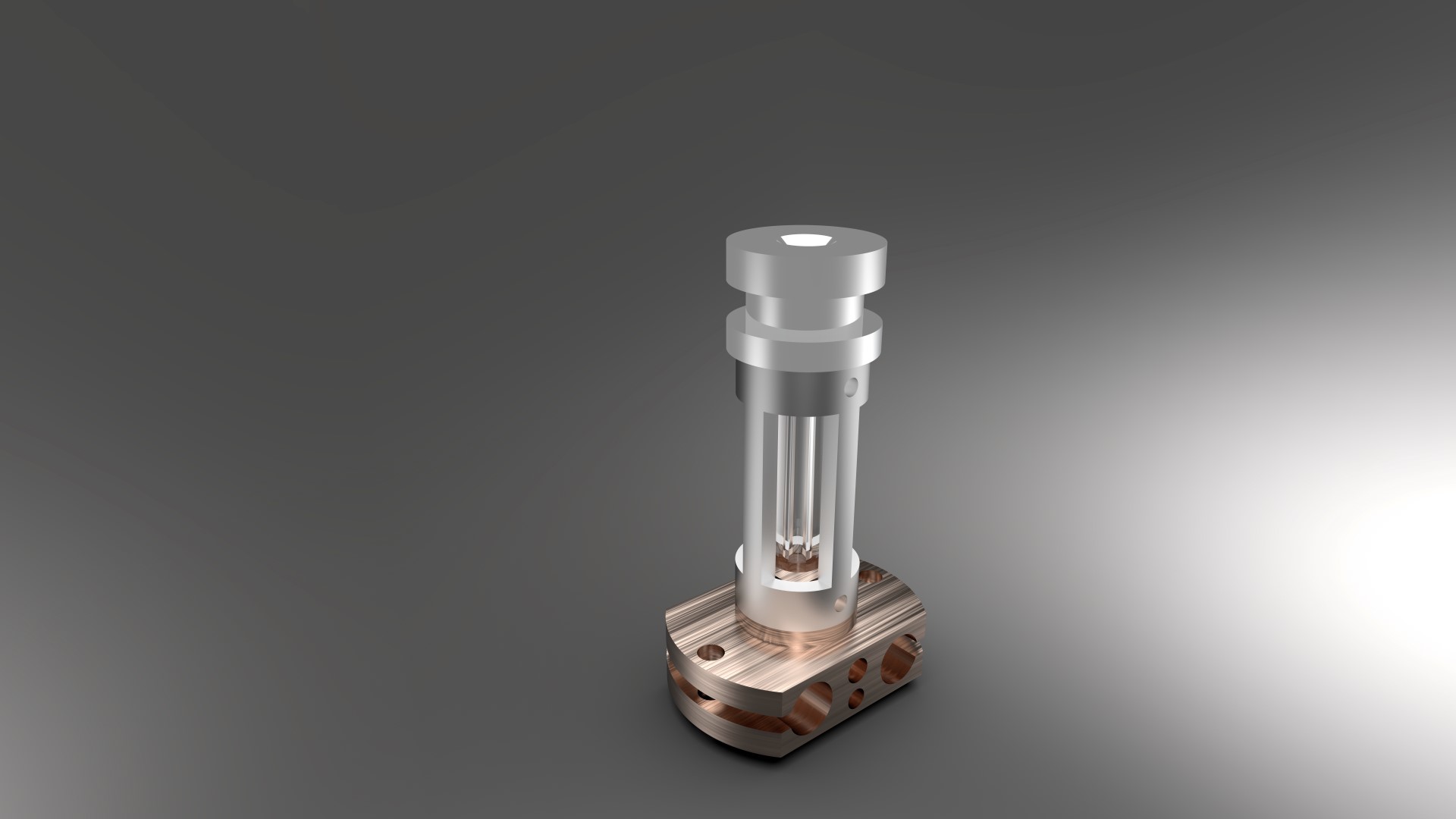
After your comments, I decided to implement a simple solution to the "unscrew" possibility, take a look at it and let me know.
Yes both cartridges will be connected to the same output via SSR. to protect the Mosfet from overload.
A2,
I been thinking of round ends instead of chamfer ones, my only concern with round ones is the possibility of misalignment due to machining but yes it will reduce any stress in the connection.
One more alternative i'm considering is use a thicker tube with a grove in both ends, and using a heated brass ring slided in the grove to serve as threading mechanism and for sealing purposes (might leak a little but will not pass the ring (see alternative1 picture) also the cost involve in this design is unknown.
Thanks for the advise, keep it coming.... I want to make this thing a reality for my Christmas present. ; )
|
Re: Quartz tube test will begin tonight, any test request? November 07, 2014 11:44AM |
Registered: 10 years ago Posts: 469 |
May I ask why use quarz glass? Regular glass should be close to what we need and much cheaper. Cutting threads in glass is a bad idea, however lapping the ends of the glass and having the glass sit in the hot end would help with leakage. At some point the plastic would burn on the edges producing a seal. I am more interested in this type of hot end to eliminate the cooling block, reducing the hot end length and printing at much much higher temps, ~300c range for cheap nylon weedwacker line. I could care less for a window, or looking at the hot end internals. It certainly is nice looking, but looks for me give way to form.
Just my .02c
Check this one out? [smile.amazon.com]
Edited 1 time(s). Last edit at 11/07/2014 11:51AM by jaguarking11.
My Personal Blog. Build blog.
[engineerd3d.ddns.net]
Modicum V1 sold on e-bay user jaguarking11
Just my .02c
Check this one out? [smile.amazon.com]
Edited 1 time(s). Last edit at 11/07/2014 11:51AM by jaguarking11.
My Personal Blog. Build blog.
[engineerd3d.ddns.net]
Modicum V1 sold on e-bay user jaguarking11
|
Re: Quartz tube test will begin tonight, any test request? November 07, 2014 12:01PM |
Registered: 10 years ago Posts: 1,401 |
|
Re: Quartz tube test will begin tonight, any test request? November 07, 2014 12:22PM |
Registered: 10 years ago Posts: 1,401 |
|
Re: Quartz tube test will begin tonight, any test request? November 07, 2014 12:35PM |
Admin Registered: 11 years ago Posts: 3,096 |
Quote
ggherbaz
Ohmarinus,
After your comments, I decided to implement a simple solution to the "unscrew" possibility, take a look at it and let me know.
Yes both cartridges will be connected to the same output via SSR. to protect the Mosfet from overload.
A2,
I been thinking of round ends instead of chamfer ones, my only concern with round ones is the possibility of misalignment due to machining but yes it will reduce any stress in the connection.
One more alternative i'm considering is use a thicker tube with a grove in both ends, and using a heated brass ring slided in the grove to serve as threading mechanism and for sealing purposes (might leak a little but will not pass the ring (see alternative1 picture) also the cost involve in this design is unknown.
Thanks for the advise, keep it coming.... I want to make this thing a reality for my Christmas present. ; )
Looks great, I wouldn't make the flats on the thread though. It takes another run with the mill and I would expect it to work by just screwing it onto the thread too.
Man, good idea to just keep the quartz as a tube. This way the quartz machining is left to a minimum and metal machining is probably cheaper anyway.
One more thing, maybe the topside of the quartz has to have the smoothed edge on the inside, to make sure the filament can't get stuck on a small edge when pushed through for the first time? Or will the quartz and metal fit together so well there won't be much of an edge from the topside of the quartz?
http://www.marinusdebeer.nl/
|
Re: Quartz tube test will begin tonight, any test request? November 07, 2014 02:29PM |
Registered: 10 years ago Posts: 1,401 |
Ohmarinus,
I can reduce the size of the flats in the threaded area, but i'm afraid that if I don't create them and screw into threads I can damage the thread and cross thread on disassembly? will ask the machinist.
the chamfer in both the aluminum top and quartz tube should be tight enough to prevent the filament from getting stuck, but since I have only one shot at this, I will add a chamfer to the inner part. Thanks for the advise.
I read some more about the borosilicate tubing, they share a lot of characteristics with quartz, should be as smooth as quartz and it is thermal shock resistant. the only concern here is the level of impurities that can affect the performance. I will get some if I can find it with my desired specs 2mm ID and 6mm OD.
|
Re: Quartz tube test will begin tonight, any test request? November 07, 2014 06:29PM |
Admin Registered: 11 years ago Posts: 3,096 |
Just a small question remains... Did you already have a name for your hotend, since, essentially, you are designing one right now! 
http://www.marinusdebeer.nl/
http://www.marinusdebeer.nl/
|
Re: Quartz tube test will begin tonight, any test request? November 07, 2014 06:31PM |
Registered: 10 years ago Posts: 1,401 |
|
Re: Quartz tube test will begin tonight, any test request? November 07, 2014 06:35PM |
Registered: 10 years ago Posts: 1,401 |

|
Re: Quartz tube test will begin tonight, any test request? November 07, 2014 06:52PM |
Registered: 10 years ago Posts: 167 |
Question.
For long duration prints, will the heat creap up the fillament to a point where the fillament outside of the hotend starts to transition? or will it not go that far?
you mention in your testing seeing the Quartz tube filing up with plastic.
For a name, how about QuartzE (pronouced quartzey) taking on the naming convention from the coreXY and coreXZ where the axes is capitalized at the end of the name (given the hot end is part of the E axes)
|
Re: Quartz tube test will begin tonight, any test request? November 07, 2014 07:46PM |
Registered: 10 years ago Posts: 1,401 |
Zerker,
On my test after 1 hour, the temperature on top of quartz pipe was 83 degrees no aluminum block or fins or nothing, actually the whole pipe was covere with kapton tape holding the thermocouple in place, after that test I proceed to print a 3 1/2 hour print but after hour and some a leaks developed and printing failed, you can see in one of the photos that the pipe cracked where meet the nozzle (assuming to much pressure) when I was disassembling the hot end the whole thing fall of my hands and broke the pipe. If filament is left inside for long periods (over 20 minutes more or less) the filament will expand up to 3/4 the length of the pipe but while printing it never went up 1/2 way.
Unfortunately test was cut abruptly and so many question still remain, but I really think this is the way to go and that's why I'm willing to put the money into further development. As to active cooling, I think it might be needed in extremely long prints, thermal conductivity of PEEK is 0.25 and quartz is 1.45, still long shot to stainless at 16 but yes temperature will raise eventually, how long it will take and if active cooling will be needed will be evaluated whit new hot end.
Most likely production of only one of them will go around 200~250 maybe more? and Christmas time is around the corner with three kids and a wife to please, of course I'm using it to to get the money.... It will be my Christmas present.
As for the name goes: you get the honors.....QuartzE will be.
Edited 2 time(s). Last edit at 11/07/2014 07:58PM by ggherbaz.
|
Re: Quartz tube test will begin tonight, any test request? November 07, 2014 07:56PM |
Registered: 10 years ago Posts: 1,401 |
|
Re: Quartz tube test will begin tonight, any test request? November 08, 2014 10:40AM |
Registered: 10 years ago Posts: 903 |
Maybe I missed something, but I thought that the whole point of using the quartz tube was as a replacement heat break? If the part in your latest drawing that wraps around the quartz is made of metal, it will likely defeat this purpose.
I think that the solution someone else pointed out above makes more sense. Use the same type of slots that you incorporated for the heater cartridges as pinch holders for the quartz tube. My only concern is that the metal would expand quicker than the quartz, allowing it to slide off as it heats up. Wrapping it with something that has a higher expansion rate than the heater block should cure that.
In terms of cost, I don't know if this is the same type of tubing that you were using, but Amazon has 2mm (ID) x 8mm (OD) tubing for about $25/meter shipped that I would think is strong enough to withstand both being clamped and a head crash or two:
http://www.amazon.com/Fused-Quartz-Tubing-Diameter-Length/dp/B00OZXQS9A/ref=pd_rhf_gw_p_img_3
There are several other sizes of tubing available, and it would be interesting to fit one tube inside a second one with clear liquid cooling for the ultimate bling hotend.....
|
Re: Quartz tube test will begin tonight, any test request? November 08, 2014 02:28PM |
Registered: 10 years ago Posts: 1,401 |
vreihen,
My original intention was to only use the quartz tube between heater block and upper connector, but the quartz tube ends up been more delicate that thought.
The middle metal piece will not transfer any heat to the quartz tube nor the filament and it is open in the middle not only for view but to limit any heat transfer to the upper body.
The quartz tube needs to be thin in order to comply with it's function, the thicker I make it the more heat will hold, I'm debating between 4mm and 6mm OD, anything thicker than that won't work at least for me.
|
Re: Quartz tube test will begin tonight, any test request? November 09, 2014 10:02PM |
Admin Registered: 13 years ago Posts: 730 |
You guys may already be aware of this, but I didn't see anyone else post these links yet. There are some very successful experiments with glass hot ends on the wiki. See Glass Nozzles and Heater Block for Glass Nozzle.
|
Re: Quartz tube test will begin tonight, any test request? November 10, 2014 12:38AM |
Registered: 10 years ago Posts: 167 |
Both of those attempt to do away with the Nozzle, this does not.
I'm sure there will be some useful information in there anyway.
@ggherbaz Thanks for the honour, I'm going to have to get one once the launch now
I cant recall where I read up on how the different zones effect pressure in the hotend, but I'm a thinking that maybe the plastic melting higher in the glass, would be considered a long melt zone? could this be what caused the pressure in the hotend that lead to the glass tube breaking? or would this still be considered transition zone, meaning that it doesn't matter how long the transition zone is (within reason) as there is so little friction between the plastic and the glass?
|
Re: Quartz tube test will begin tonight, any test request? November 10, 2014 02:00AM |
Registered: 10 years ago Posts: 1,401 |
Zerker,
While printing, the melting zone was barely seen in the tube, between heater block and cooling block was 13mm separation, from the heater block up about 2mm was definitely melted and about 7~9mm was in the transition zone, the way you see it is that the melted filament was swelled against the walls of the tube the other part of the filament would look really shine "glass like " but not swollen. The melting zone most likely was about 9mm total since threaded portion on the lower part was 7mm. Extruding by hand felt the same as a ss barrel with PTFE liner. So the same amount or almost the same of melted and in transition for a total of 18mm out of the 30mm total length of the pipe.
Now that evaluation I left it for the more knowledgeable people, what it means or if great, good or poor I don't know. I'm looking to solve a problem that I have and that is that I print with too many different filaments from PLA to polycarbonate to laywood and everything in between, and I have to jump between printers because one hot end can't do it all (sorry e3d v6) still not there for me, and trying to see ahead into the future with higher temp filaments.
The pipe broke for two reasons: 1 pressure/stress (tightening the metal nozzle against the glass) and 2 impact, no extrusion caused the breakage.
Tomorrow i'm meeting with an old friend that has the mill to do the parts and I already sent the new pipe design to the ones that make me the old ones.
Edited 1 time(s). Last edit at 11/10/2014 02:08AM by ggherbaz.
|
Re: Quartz tube test will begin tonight, any test request? November 10, 2014 02:37PM |
Registered: 10 years ago Posts: 469 |
To add to this, one of the main reasons people have success with the j-head is because it has the transition phase is in the metal part of the hot end. The rest of it is purely insulation in my book.
The glass, or ceramic would be a much better solution to peek and teflon liners. The only thing that is missing from this design is an adjustable melt zone in the nozzle. From observing my printer with nozzles ranging from .4mm to .5mm, to 1.54mm I can say that these constants were observed.
The larger the extrusion nozzle there is the shorter the transition phase should be, to keep this in check and working you need two other variables tweaked. The thermal mass of the melt chamber should be higher when using large orafice, and the temperatures should be higher. My modified j-head only worked properly when above 230c while using a larger orafice, and worked very well at 250c, which causes the j-head to rapidly degrade.
On the flip side, the thermal mass should be lower when the nozzle is smaller and the transition zone longer.
To properly have a balanced hot end in my book it needs the following properties.
1 - glass/ceramic thermal insulator.
2 - long barrel (cermic or glass) A proper clamping mechanism needs to be worked out.
3 - adjustable thermal block (changing the transition zone from very short, to much longer) (~5mm should do it)
4 - quick change nozzles.
5 - thermal insulation of the heater block.
One other thing I observed when looking at commercial printers, is that they use ceramics as an insulator for the thermal block, not only that but they use a fairly high thermal mass across the board.
To further add to my ramblings. We can 3d print ceramic insulators, the problem is firing them to proper tensile strength. The ceramic insulator can be shaped after printing with a piece of polished glass tubing to hold the shape and smoothness while drying and before firing it. These ceramics can withstand 2000-3000c ranges. Not a bad way to go......
My Personal Blog. Build blog.
[engineerd3d.ddns.net]
Modicum V1 sold on e-bay user jaguarking11
|
Re: Quartz tube test will begin tonight, any test request? November 10, 2014 03:00PM |
Registered: 10 years ago Posts: 564 |
Quote
jaguarking11
To add to this, one of the main reasons people have success with the j-head is because it has the transition phase is in the metal part of the hot end. The rest of it is purely insulation in my book.
The glass, or ceramic would be a much better solution to peek and teflon liners. The only thing that is missing from this design is an adjustable melt zone in the nozzle. From observing my printer with nozzles ranging from .4mm to .5mm, to 1.54mm I can say that these constants were observed.
The larger the extrusion nozzle there is the shorter the transition phase should be, to keep this in check and working you need two other variables tweaked. The thermal mass of the melt chamber should be higher when using large orafice, and the temperatures should be higher. My modified j-head only worked properly when above 230c while using a larger orafice, and worked very well at 250c, which causes the j-head to rapidly degrade.
On the flip side, the thermal mass should be lower when the nozzle is smaller and the transition zone longer.
To properly have a balanced hot end in my book it needs the following properties.
1 - glass/ceramic thermal insulator.
2 - long barrel (cermic or glass) A proper clamping mechanism needs to be worked out.
3 - adjustable thermal block (changing the transition zone from very short, to much longer) (~5mm should do it)
4 - quick change nozzles.
5 - thermal insulation of the heater block.
One other thing I observed when looking at commercial printers, is that they use ceramics as an insulator for the thermal block, not only that but they use a fairly high thermal mass across the board.
To further add to my ramblings. We can 3d print ceramic insulators, the problem is firing them to proper tensile strength. The ceramic insulator can be shaped after printing with a piece of polished glass tubing to hold the shape and smoothness while drying and before firing it. These ceramics can withstand 2000-3000c ranges. Not a bad way to go......
A couple of questions:
1. You say you want a longer transition zone with a smaller diameter nozzle - why is that? Seems like a short transition zone will always produce less friction in the tube.
2. You recommend a long barrel (presumably for the thermal break/insulator tube). Discounting convective and radiant cooling from the tube, you should get more or less a uniform temperature gradient form the hot end to the cold end. Seems like a longer tube would stretch out the temperature gradient and give you a longer transition zone.
I don't have that much experience with different hot-ends so I'm just trying to see what I'm missing.
|
Re: Quartz tube test will begin tonight, any test request? November 10, 2014 04:01PM |
Registered: 10 years ago Posts: 469 |
Longer transition zone with lower temps I feel will result in less pressure to print and less time to burn.
Shorter transition zone and larger thermal mass seems like a good idea for large orafice printing. My printer is capable of printing large objects, the problem is that if the nozzle is fine the print time is very long. Longest so far I have had was 12+ hours with a .4mm nozzle. However if I want a larger object, resolution is not as important, speed is. I can always post process something large fairly quickly vs printing at very high resolution. My goal is to have .5-.8mm layer thickness when I print very large parts, this would ensure a much quicker print time.
The front panel on my printer with a .4mm nozzle with .2mm layer height took 6-7 hours and it warped badly. A larger version of said panel with 1.54mm nozzle and .5mm layer height took 1hour and 20 minutes flat. Huge gain in time. 5 minutes worth of sanding ensured it works very well. However some tweaking of the design was necessary. nothing can have a wall less than 1.5mm. The width with 1.5mm nozzle was nearly 3mm wide when printing at .3mm height, and nearly 2.2mm wide when printing with .5mm height. This allowed me to accelerate the printer considerably, not only that but it allowed me to reduce the nozzle pressure, but it required 230C+ temps just to keep up with the plastic flowing. The plastic melting has its own cooling effect on the nozzle. I have a hunch that when your transition zone is longer, you can print with higher resolution better and reduce the chances of it clogging. The finer the nozzle, the more viscous the plastic has to be, but to achieve the right viscosity you have to add heat, the higher the heat, the higher the chance of it charring and burning in the nozzle, causing a clog. To remedy this, you bring your nozzle to a sharp temp, but feed preheated filament into it, this will reduce the time the plastic spends in the melt chamber, which should be much smaller now and reduces the chance of the plastic charring up.
The oposide is true of larger nozzle, you want to have a much larger melt chamber to keep the plastic flowing. The problem with this is that all nozzles on the market have a very short melt chamber, then you add a larger nozzle, it will clog. So what do you do? You increase heat. This weakens the Peek, or teflon that is now running close to 260c. It will break down quick. I had my j-head emit smoke out of the hot end due to the teflon, the peek also got quite soft. I have a feeling that after 10-15 hours of use the head will be ready for the trash. The glass tubing comes into play here, but not as a melting point, but as a thermal insulator. At least in my book. I will be ordering some glass tubing and experimenting with it soon enough. Id like to be able to extrude as high as 300c. I also found thermal probes that work up to 350c. Time will tell how this works though.
Having a hot end that can accommodate both fine nozzle and large nozzle means you need to play with melt zone length at the very least. I know most reprapers want ever increasing resolution, however for me I want ever increasing speed. Only going to fine nozzles when I need to print things with very high detail. The rest will be printed at low resolution and high speed.
Attached you will find my front panel pic. its nearly 230mm long by 180mm wide by 40mm high.
My Personal Blog. Build blog.
[engineerd3d.ddns.net]
Modicum V1 sold on e-bay user jaguarking11
|
Re: Quartz tube test will begin tonight, any test request? November 11, 2014 09:11PM |
Registered: 10 years ago Posts: 1,401 |
LoboCNC,
jaguarking11 explained very good, but here is my side of the story:
I just finished a 36 hour print, and that's pretty much my standard, the fastest print I have done is 9 hours. The last piece requested was print on PLA at 0.1 layer height and 90% infill, yes I can increase temperature and try to print faster, but then quality suffer and if someone is paying me 70 to 90 dollars for a piece it needs to be perfect to the tee, some times I have to re print a part because something didn't look right at the 99% mark. Some times I see parts from vendors that makes me cry, I meant crap you are selling a printer and you supply such a bad printed part? Going to the point, a longer transition zone and a shorter melt zone is what I'm looking for and here is the reason, the melted filament is what you have ready for extrusion, if you need to print faster that parts goes quick then you need to melt the next portion to be used, if your melted zone is short, by the time you melt it it's gone and the next portion isn't ready yet (your transition zone is gone) and next you hear a clicking noise coming out of your extruder, if you have a longer transition zone and with the use of dual heaters, any portion of that zone that gets melted the same amount will get in transition.
Out of my short by valuable observations (to me) the transition zone do not create any friction and actually moves better inside the tube, it's the melted zome the one creating the friction so in theory a shorter melted zone will reduce friction, figure a 10 mm cylinder with a 10 mm piston (cylinder=tube piston=filament) and you press the piston to move oil, with one stroke you will be moving all the oil out of the cylinder, now change that piston to an 8mm, what happens? You still pull out some oil but some will slide up and that's exactly what its going inside that tube.
My test resulted in an equal size zones. 9mm each (approximately) I want to go at least 9 and 12~14mm increasing length is the only way because if I increase temperature I will be increasing the melted zone too.
So in theory and just in theory I could print faster without having to increase temperature and loosing quality due to it.
Edited 2 time(s). Last edit at 11/11/2014 09:25PM by ggherbaz.
|
Re: Quartz tube test will begin tonight, any test request? November 11, 2014 09:23PM |
Registered: 10 years ago Posts: 1,401 |
|
Re: Quartz tube test will begin tonight, any test request? November 12, 2014 04:24AM |
Admin Registered: 11 years ago Posts: 3,096 |
Quote
ggherbaz
LoboCNC,
jaguarking11 explained very good, but here is my side of the story:
I just finished a 36 hour print, and that's pretty much my standard, the fastest print I have done is 9 hours. The last piece requested was print on PLA at 0.1 layer height and 90% infill, yes I can increase temperature and try to print faster, but then quality suffer and if someone is paying me 70 to 90 dollars for a piece it needs to be perfect to the tee, some times I have to re print a part because something didn't look right at the 99% mark. Some times I see parts from vendors that makes me cry, I meant crap you are selling a printer and you supply such a bad printed part? Going to the point, a longer transition zone and a shorter melt zone is what I'm looking for and here is the reason, the melted filament is what you have ready for extrusion, if you need to print faster that parts goes quick then you need to melt the next portion to be used, if your melted zone is short, by the time you melt it it's gone and the next portion isn't ready yet (your transition zone is gone) and next you hear a clicking noise coming out of your extruder, if you have a longer transition zone and with the use of dual heaters, any portion of that zone that gets melted the same amount will get in transition.
Out of my short by valuable observations (to me) the transition zone do not create any friction and actually moves better inside the tube, it's the melted zome the one creating the friction so in theory a shorter melted zone will reduce friction, figure a 10 mm cylinder with a 10 mm piston (cylinder=tube piston=filament) and you press the piston to move oil, with one stroke you will be moving all the oil out of the cylinder, now change that piston to an 8mm, what happens? You still pull out some oil but some will slide up and that's exactly what its going inside that tube.
My test resulted in an equal size zones. 9mm each (approximately) I want to go at least 9 and 12~14mm increasing length is the only way because if I increase temperature I will be increasing the melted zone too.
So in theory and just in theory I could print faster without having to increase temperature and loosing quality due to it.
Good to hear, it seems you are a true craftsman.
Would there be any place where you have a 'showcase' of your prints? I am very curious!
http://www.marinusdebeer.nl/
|
Re: Quartz tube test will begin tonight, any test request? November 12, 2014 07:43AM |
Registered: 10 years ago Posts: 1,401 |
Ohmarinus,
Thanks, I wish I really was one, but more of a stubborn guy than anything else....
[forums.reprap.org]
That's an example, it's my own design and yes. I haven't post it yet on thingiverse.
Attached is the infamous 36 hour print, I'm in 3D Hubs under Gerardo and my wife is working on the website 3Do-it.com
There is not much to show unfortunately, most of my prints falls under the non disclosure agreements that I sign for my customers.
For most of the prints I use a heavily modified CTC printer that I bought back in February for $ 650. I kicked my own butt for about 4 to 5 months to learn how to print properly and not wake up with an air print. Still scared me every 24 plus hours print, but at this point I'm little more confident in my abilities and the functionality of my printer.
Edited 2 time(s). Last edit at 11/12/2014 07:56AM by ggherbaz.


Sorry, only registered users may post in this forum.