LISA Simpson
Posted by nicholas.seward
|
Re: LISA Simpson January 06, 2014 07:41AM |
Registered: 10 years ago Posts: 1,433 |
The plate I'm looking at is a 18.6875" diameter 1.25 thick cast aluminum tooling plate:
[www.ebay.com]
It's already nice and round so it will drop right in.
At this point the heater is just a check mark on the list. I'm not real sure it will be part of the initial build.
The main component of the horizontal structure is still ¾” plywood. I have not settled on an exact lay up yet. I’m not planning on using the aluminum plate for structure. It will just sit on top of the plywood and act as ballast.
Edited 1 time(s). Last edit at 01/06/2014 12:25PM by uncle_bob.
|
Re: LISA Simpson January 06, 2014 03:24PM |
Registered: 10 years ago Posts: 1,381 |
Quote
uncle_bob
I’m not planning on using the aluminum plate for structure. It will just sit on top of the plywood and act as ballast.
34 lbs seems light for ~5 foot tall structure, is there a future use for it besides ballast?
Heating a large mass will aid in maintaining a consistent enclosure temperature.
(Cool aluminum disk
 )
)I'm using cement, and to achieve a flat surface, it will be cast on top of a pane of glass.
It's possible that the open mold side could be made parallel if you level the pane of glass beforehand,
and add a layer of self leveling cement.
I'm estimating that the total weight will be between ~50 to 100 lbs.
When the assembly drawing is completed I'll know where the center of the mass is located.
I'll make adjustments at that time.
Quote
uncle_bob
I have not settled on an exact lay up yet.
If you sandwich fiberglass cloth and epoxy between the plywood that will help keep it stable.
Orientate the plywood to a 90 degree bias of the skin grain.
I imagine that glue alone will work very well.
Wood is among the most thermally stable materials in the world, exceeding steel by a factor of 2.
But moisture absorption disrupts the dimensional stability of wood,
mostly tangentially, and radially, expansion due to moisture parallel-to-grain is very stable.
So sealing the wood is a good practice, after drying it.
I'm using cedar for the arms.
Its coefficient of thermal expansion parallel-to-grain is 0.0000028 in./in./degree F.
[inspectapedia.com]
[www.fs.fed.us]
|
Re: LISA Simpson January 06, 2014 07:11PM |
Registered: 10 years ago Posts: 1,433 |
The stepper motors and the rest of the "stuff" will add to the ballast. I can always add more if I need to. I'd prefer to keep this light enough to move up and down stars if possible. That may not be practical.
I've been fighting the moisture effect on plywood with my current printer. Turn on the heated bed and two days later you have a potato chip where you used to have a flat surface. The heated bed drys out the face that's towards the bed....
The fiberglass / epoxy sandwich approach does have some appeal. It's fairly easy to do and it would help stabilize the the surface layer(s) of the plywood. I'm a bit concerned about pushing bearings right through the plywood as I tighten things up.. I'm hoping I can find some really big 3/4" washers.
|
Re: LISA Simpson January 07, 2014 01:39PM |
Registered: 10 years ago Posts: 219 |
Quote
A2
Neri Oxman
3-D printing buildings of the future
[www.youtube.com]
Neri Oxman
Is it possible to 3-D print buildings?
[www.youtube.com]
Well, that does answers the question wheter there are (good looking) females in 3D printing !
What was the video about anyway?

Blogs:
Meine 3D Druck Abenteuer
[3dptb.blogspot.de]
FLSUN Delta Drucker für Deutschland
[flsun-deutschland.blogspot.com]
Books on 3D patents:
[goo.gl] (english)
[www.amazon.de] (deutsch)
|
Re: LISA Simpson January 07, 2014 03:23PM |
Registered: 11 years ago Posts: 979 |
I just discovered vented screws. They are normal socket cap screws with holes predrilled. M8's happen to have 2mm holes. I think I might get some and try to convert my hub back to 608s. They are a little pricey. The 6702 are probably cheaper but this will give you a more solid hub axle. It will be a fun experiment either way.
[www.mcmaster.com]
[www.mcmaster.com]
|
Re: LISA Simpson January 07, 2014 05:11PM |
Registered: 10 years ago Posts: 1,433 |
Speaking of discoveries:
I have found a source for pretty good plywood with thickness options of ¾, 1, and 1 ½”. The stuff isn’t exactly cheap. My guess is that on a 2X larger printer, ¾ by it’s self isn’t going to do the for the horizontal plate in the middle of the stack. It *might* be thick enough for the top or bottom plate in the stack. I’d also bet that 1.5” is thick enough by it’s self for the middle plate in the stack.
[www.buyappleply.com]
More or less the idea:
Motors mount to the middle plate (below it), so the bottom plate is not got a lot on it – use ¾”
Middle plate has a lot on it and a lot going on - use 1 ½”
Top plate still has a lot going on – use 1”
The question to the group – is that enough?
|
Re: LISA Simpson January 07, 2014 05:56PM |
Registered: 10 years ago Posts: 1,381 |
Quote
nicholas.seward
I just discovered vented screws. They are normal socket cap screws with holes predrilled. M8's happen to have 2mm holes. I think I might get some and try to convert my hub back to 608s. They are a little pricey. The 6702 are probably cheaper but this will give you a more solid hub axle. It will be a fun experiment either way.
[www.mcmaster.com]
Good idea, but the longest vented SHCS is only 40 mm, is that enough?
|
Re: LISA Simpson January 07, 2014 06:16PM |
Registered: 10 years ago Posts: 1,381 |
Quote
uncle_bob
Speaking of discoveries:
I have found a source for pretty good plywood with thickness options of ¾, 1, and 1 ½”. The stuff isn’t exactly cheap. My guess is that on a 2X larger printer, ¾ by it’s self isn’t going to do the for the horizontal plate in the middle of the stack. It *might* be thick enough for the top or bottom plate in the stack. I’d also bet that 1.5” is thick enough by it’s self for the middle plate in the stack.
[www.buyappleply.com]
More or less the idea:
Motors mount to the middle plate (below it), so the bottom plate is not got a lot on it – use ¾”
Middle plate has a lot on it and a lot going on - use 1 ½”
Top plate still has a lot going on – use 1”
The question to the group – is that enough?
The top and bottom platens really don't experience any loading, they just maintain the positions of the lead screw.
The middle substrate can be bolstered with jack-screws, turn buckles, wooden support post, etc to the bottom platen.
I need to see a CAD data file to make a sound suggestion, that said here's an idea to consider.
I like the idea of using wooden dowels pocketed and glued to the middle substrate and bottom platen.
This will allow you to use thinner, less expensive material alternatives.
Process:
1 Clamp together the middle substrate and bottom platen together.
2.1 Drill holes through both pieces of plywood where you want the supports located.
2.2 Drill Alternative: you can drill through the bottom platen,
and machine a pocket on the back side of the substrate to preserve the surface finish.
3 Separate the two platens with an object of consistent height, (e.g. 1-2-3 blocks).
4 Insert wooden dowels, and glue.
5 Excess dowel length should protrude through the bottom platen.
6 Cut excess off.
Did you figure out a method to mount the lead screw bearings to the top platen?
Edited 1 time(s). Last edit at 01/07/2014 07:25PM by A2.
|
Re: LISA Simpson January 07, 2014 06:35PM |
Registered: 10 years ago Posts: 1,433 |
If you are using 608's and you have 4 bearings in the stack, that would use up 28 mm of your 40 mm. A thin 8mm nut will add 2.7 mm. You are down to about 9.3 mm for spacing and what ever you are attaching to on the bottom of the stack.
These guys:
[onlinecatalog.tpa-us.com]?
Will sell you 5 pcs that are 60 mm long for only $97.07.....
These guys go to 50 mm for $15.19
[barnhillbolt.com]
Edited 1 time(s). Last edit at 01/07/2014 06:48PM by uncle_bob.
These guys:
[onlinecatalog.tpa-us.com]?
Will sell you 5 pcs that are 60 mm long for only $97.07.....
These guys go to 50 mm for $15.19
[barnhillbolt.com]
Edited 1 time(s). Last edit at 01/07/2014 06:48PM by uncle_bob.
|
Re: LISA Simpson January 07, 2014 06:41PM |
Registered: 11 years ago Posts: 979 |
@uncle_bob: If you mount the steppers to the midplate where do the bearings go.
On that note. I am moving my design to 4 plates. 5 if you count under the basalt.
I will have the bottom plate which will have nothing mounted on it. Just 3 holes for tensioning the pressure column.
I will have a downward facing electronics plate. The power supply and the controller is on the bottom of it. The face of the steppers are on the bottom of this plate.
I will have an elevated bearing plate that has a big hole in the middle so the extruder can extend past this plate to the build platform.
The top plate will have another 3 bearings.
Mounted above the electronics plate on stiff springs tensioned with M8's with big printed thumb screw attachments will be the build platform. It will actually be a wooden seat for the hot bed with the basalt on top.
This whole new design will have the columns pulled in like you are doing yours.
What do you think? This will add about 75mm to the build height. So I will be pushing a 200mm diameter by 300mm tall build volume.
This will also bring the bearings closer together making the machine more rigid.
|
Re: LISA Simpson January 07, 2014 06:46PM |
Registered: 11 years ago Posts: 979 |
Quote
uncle_bob
If you are using 608's and you have 4 bearings in the stack, that would use up 28 mm of your 40 mm. A thin 8mm nut will add 2.7 mm. You are down to about 9.3 mm for spacing and what ever you are attaching to on the bottom of the stack.
These guys:
[onlinecatalog.tpa-us.com]?
Will sell you 5 pcs that are 60 mm long for only $97.07.....
I guess that brings me back to this [www.mcmaster.com]
Is $16 worth it. I get 6702s for about $1-$2 and 608s are 25cents. So is a net $13 worth getting a metal axle?
|
Re: LISA Simpson January 07, 2014 07:20PM |
Registered: 10 years ago Posts: 1,381 |
Quote
nicholas.seward
Quote
uncle_bob
If you are using 608's and you have 4 bearings in the stack, that would use up 28 mm of your 40 mm. A thin 8mm nut will add 2.7 mm. You are down to about 9.3 mm for spacing and what ever you are attaching to on the bottom of the stack.
These guys:
[onlinecatalog.tpa-us.com]?
Will sell you 5 pcs that are 60 mm long for only $97.07.....
I guess that brings me back to this [www.mcmaster.com]
Is $16 worth it. I get 6702s for about $1-$2 and 608s are 25cents. So is a net $13 worth getting a metal axle?
The No1 goal is to reduce end effector slop, correct?
I like the concept a lot, and I would like to see a prototype.
If you can eliminate all slop, then the price is worth it.
Will a 4 mm bearing width anchor well enough so it's not loose, or works loose over time/enclosure temp?
With a 15 mm ID, you'll be using a Dia 0.500" stud, it will be too loose.
The stud needs to be pressed fit into the bearing to reduce the slop.
Or am I missing some thing important with the design?
6702
[www.vxb.com]
4 mm = Width 0.157"
15 mm = Dia 0.590"
|
Re: LISA Simpson January 07, 2014 07:33PM |
Registered: 11 years ago Posts: 979 |
@A2: While press fit bearings is a good idea it isn't hobby friendly. I use 5/16" or M8 bolts though 608s as my standard setup. However, the bearings always come in pairs and I tension the setup so the slop is completely removed. There is slop and then there is misalignment. In my setup there may be a slight misalignment but the slop will be zero.
|
Re: LISA Simpson January 07, 2014 07:46PM |
Registered: 10 years ago Posts: 1,433 |
Multi plate approach:
I'm probably missing something very basic about mounting the motors and bearings. My approach is based on NEMA-23's and putting the bearing on the plate that's above the motors. The bearings should be small enough in O.D. to fit inside the bolt pattern on the face of the motor. Drop a few hollow spacers between the motor face and the board above it. Put bolts through the motor face holes, through the spacer, through the plywood, tighten them down.
Plate count:
Bottom plate with tension nuts for the thread rod and the casters on it, nothing else down here - same / same
second plate with electronics on the bottom - you have motors / I run the motor screws into the next plate up (I assume the build plate rests on this one)
third pale - interesting idea - I would mount both the motors and bearings on this one
top plate - bearings and nuts to tension the drive shafts same / same.
metal hub:
I'm still not quite sure that 40 mm is enough length. Even more so if they are measuring the head in the length. (I've run into that one as I've searched).
These guys:
[www.sdp-si.com]
Will sell you some 35 mm aluminum hollow shaft (35mm) for $30. You still have a few other things to get done....
|
Re: LISA Simpson January 07, 2014 08:00PM |
Registered: 10 years ago Posts: 1,433 |
slop:
The other driver for the metal shaft on a large printer is to drop the hub diameter. If you scale everything up, the hub gets fairly large.
sunken build plate:
One concern would be sinking things far enough that getting the part off the machine would be harder. If you printed a "thing" that completely filled the build volume, tilting it to get it off only would help to a certain degree.
Edited 1 time(s). Last edit at 01/07/2014 08:49PM by uncle_bob.
|
Re: LISA Simpson January 07, 2014 09:21PM |
Registered: 10 years ago Posts: 1,381 |
Quote
uncle_bob
slop:
The other driver for the metal shaft on a large printer is to drop the hub diameter. If you scale everything up, the hub gets fairly large.
I imagine that some things don't need to be scaled, and can be accounted with a variable change or code modification.
You should be able to modify the g-code preprocessor math to account for a portion of the design to be not scaled (original design intent),
such as the pivot distance of the hub/end effector, and if necessary the lead screw nut pivot distance from the lead screw.
I'm making changes that will necessitate modifications to the g-code preprocessor math:
I'm eliminating the arm pivot off sets, this will place the arms in-line with the lead screw and end effector (math reduction).
I haven't studied the math so I don't know what the function is doing at this time,
but it might be that I only need to delete a portion of the math.
From this
return [z+thetas+math.sqrt(arm_length**2-(ds-hub_offset-shoulder_offset)**2) for i in range(3)]
to this
return [z+thetas+math.sqrt(arm_length**2-(ds)**2) for i in range(3)]
I want a double shear joint vs. a single shear joint.
By moving the lead screw nut pivot out, and away from the lead screw (toward the hub),
you can gain enough room for the arm to drop nearly vertical.
This modification may reduce the effective build area, but it's a design goal of mine to increase the stiffness/rigidity,
and the weight bearing capability of the arms.
So I'll have to make some g-code preprocessor changes to account for the new locations of the arm component pivots, and lengths.
I'm not designing this just for me, I want others to be able to use it for more than 3d filament printing.
|
Re: LISA Simpson January 07, 2014 09:38PM |
Registered: 11 years ago Posts: 979 |
@A2: I know how to get the shoulder pivot offset to zero but I am at a loss at how you can do it with the hub offset. Well, I know several ways but none of them greatly improve the rigidity of the system.
I am all for the double shear connection. I just do the one sided connections to make assembly easier and to make LISA more tolerant of poorly printed parts. You can get away with a lot when you are only depositing plastic.
I am all for the double shear connection. I just do the one sided connections to make assembly easier and to make LISA more tolerant of poorly printed parts. You can get away with a lot when you are only depositing plastic.
|
Re: LISA Simpson January 07, 2014 09:51PM |
Registered: 10 years ago Posts: 1,433 |
If the arm is going to be able to drop straight down, the other two arms need to be a bit longer. More or less the arms get into the 1X rod spacing rather than 2/3 spacing vicinity. That either costs you build height or makes the machine taller. To be same / same I think you need to compare equal build heights.
The same is true of the straight line vs offset arms. Loosing ~ 2" of build diameter (or worse radius) is a pretty substantial hit to the design. Things then get a bit bigger X and Y to be back where you started.
With inline arms, there's still the "kink" in the arm at the drive shaft. You loose some of the math, but you still are not back to simple stuff. I don't think you are back to the "built into Marlin" math. I haven't dug into it, so I may be wrong there.
|
Re: LISA Simpson January 07, 2014 10:00PM |
Registered: 10 years ago Posts: 1,433 |
|
Re: LISA Simpson January 08, 2014 03:00AM |
Registered: 10 years ago Posts: 1,381 |
Quote
uncle_bob
I'm probably missing something very basic about mounting the motors and bearings. My approach is based on NEMA-23's and putting the bearing on the plate that's above the motors. The bearings should be small enough in O.D. to fit inside the bolt pattern on the face of the motor. Drop a few hollow spacers between the motor face and the board above it. Put bolts through the motor face holes, through the spacer, through the plywood, tighten them down.
How are you assembling the bearing to a piece of plywood?
Will you epoxy the bearing to the wood, trap the bearing between plates, etc?
Quote
nicholas.seward
I am at a loss at how you can do it with the hub offset.
What caught my attention were the parameters (variables) that had a declared offset value.
What I don't understand is why both of the offset values are not the same.
I figured there was geometry that I couldn't see in the videos.
Your confusion, is because I don't know exactly where the hub_offset dimension is taken from.
I made the assumption that if both of the input values could be changed to zero, that would be
the equivalent of the arms being located in-line with the center lines of the lead screw, and the end effector.
I assumed that the math wouldn't bomb if I deleted these two variables.
Based on your comment, it sounds like I should use the hub_offset parameter.
"""PARAMETERS"""
shoulder_offset=37.5
hub_offset=50
Quote
uncle_bob
If the arm is going to be able to drop straight down, the other two arms need to be a bit longer. More or less the arms get into the 1X rod spacing rather than 2/3 spacing vicinity. That either costs you build height or makes the machine taller. To be same / same I think you need to compare equal build heights.
I agree, you give up build envelope volume by placing the arms in-line,
and it should be compared to a Cartesian external printer footprint, and print volume size.
I have a couple of in-line joint design in mind to maximize the space.
Quote
uncle_bob
I don't think you are back to the "built into Marlin" math. I haven't dug into it, so I may be wrong there.
Why not?.... I think you're correct in your reasoning.

I had to watch a few belt driven delta printers operate, and in-line arms look to my eye to be equivalent to the belt/string deltas.
Motor rotates, belt moves a distance.
Motor rotates, nut moves a distance.
Does this mean that there could be two approaches to achieve the same calculation.
Use the g-code preprocessor to calculate only the distance.
or
Create a line of code, or add a table in the Marlin firmware of the ratio of steps to distance traveled.
Quote
uncle_bob
Bronze nuts for the Hi-Lead screws came in today. No screws to try them on yet.
They are bronze colored and heavy, beyond that nothing really useful to report about them.
Hopefully the screws will get here soon.
It might be beneficial for use at a latter date, to make an impression of the ID of the Roton nut with maybe some thing like Oogoo.
How much were they, and the shipping cost. I would like to add this expense to my BOM. This will allow me to compare the cost of having the nuts printed or making my own.
|
Re: LISA Simpson January 08, 2014 03:45AM |
Registered: 11 years ago Posts: 979 |
The shoulder offset is the distance from the center of the screw to the center of the arm attachment. The hub offset is from the central axis of the hub to the attachment of the other side of the arm. The is really no math savings in changing the geometry to eliminate them and it won't become like a Rostock. The shoulder rotation causes a translation and that has to be accounted for regardless of the offsets. You could make this have the Rostock math by adding traditional rails like a rostock and have a bearing pivot instead of a screw pivot for the shoulders.
|
Re: LISA Simpson January 08, 2014 04:32AM |
Registered: 10 years ago Posts: 1,381 |
Quote
nicholas.seward
The shoulder offset is the distance from the center of the screw to the center of the arm attachment. The hub offset is from the central axis of the hub to the attachment of the other side of the arm. The is really no math savings in changing the geometry to eliminate them and it won't become like a Rostock. The shoulder rotation causes a translation and that has to be accounted for regardless of the offsets. You could make this have the Rostock math by adding traditional rails like a rostock and have a bearing pivot instead of a screw pivot for the shoulders.
Tks for the explanation, now I understand that there is a difference in the offsets of the stub arm of the hub, and the shoulder joint of the lead screw.
They looked the same to the unaided eye, but now that I'm aware of it, I think I understand why they are not the same.
I'm interested in what the final math will be so you can use double shear joints, with in-line arms.
With in-line arms the hub offset is being eliminated.
It seems like the preprocessor code would work if the hub offset value was changed to zero for the in-line arms/double shear joint configuration.
I only suggested deleting the offset variables because it didn't' appear they were needed.
But if you can set the hub offset to zero, and that will make the preprocessor code calculate correctly for in-line arms,
then that would be a useful solution for those who need in-line arms.
|
Re: LISA Simpson January 08, 2014 07:49AM |
Registered: 10 years ago Posts: 1,433 |
Bearing mont:
Right now my *guess* on the mount is a printed part. The bearing is captive horizontally, but free vertically. It rests on a (hopefully large) washer (or two). The washer is also captive horizontally and free vertically. The printed piece mounts to the plywood with the four bolts that also hold the motor in place after the bolts go through the spacers.
Bronze nuts:
The nuts are about $37. The plastic version is about $35. The bronze parts are not available for all of the screw types. I have some of the plastic flange nuts as well. Right now the idea is to use the plastic nuts for the motion end of things and the bronze nuts to captivate the ends of the rods. Drilling and tapping bronze for a set screw sounds like a reasonable thing to do.
All of that changes several times a day plan wise....
Raised plate:
I wonder if you could simply mount a third bearing on the shafts about 1/2 way up the shaft. Tie it off to the mounting tube next to the shaft. Simple assembly to hold it in place.
|
Re: LISA Simpson January 08, 2014 08:44AM |
Registered: 11 years ago Posts: 979 |
|
Re: LISA Simpson January 08, 2014 01:04PM |
Registered: 10 years ago Posts: 1,433 |
Quote
nicholas.seward
@uncle_bob: Won't you have carriage interference if you mount bearings in the middle?
Yes indeed you would have interference. That's a very real limit to how high you could put the bearings. I'd have to do some modeling to figure out how high they can be (or if it makes sense at all). My motors are pretty tall. The same issues may apply to mounting them above the build plate. I’m guessing the motors plus “stuff” will be 8” to 10”.
-------------
Plate with dowels:
Somehow I missed the comments on the stack up. I suspect
 but will deny it if pressed...
I'd rather keep the build plate free floating from the support if possible. That way I can fiddle it with three screws to get everything close.
My alternative plan is to go with the better grade of Home Depot plywood (the Columbia PureBond stuff). I'd probably stiffen it with a couple pieces of poplar 2x2's. I can easily get three of my horizontal plates out of a 4’x8’ sheet. More or less it’s a 3 plate or 6 plate design if I go this way.
[homedepotpurebond.com]
Anything that involves major machining of 20" diameter objects is going to cost me something (beer or what ever). A few holes here or there with a drill press - no problem.
Coupler:
The only real CNC item that is still on the list is the coupler between the bottom of the drive shaft and the top of the motor. With high torque motors and no flat on the shaft, I’m not real sure that a printed part is going to get the job done. I’m guessing that epoxy will do fine for attaching one of the bronze nuts to the bottom of the shaft. That leaves me with a fairly simple round piece to go to the motor shaft and to glue in the other end of the nut. I’d love to find an off the shelf 8mm coupler that would drop into the nut. So far no luck.
..... of course this could be the perfect excuse to buy a small lathe....
Edited 1 time(s). Last edit at 01/08/2014 05:10PM by uncle_bob.
|
Re: LISA Simpson January 09, 2014 04:00AM |
Registered: 10 years ago Posts: 1,381 |


@nicholas.seward,
Quote
nicholas.seward
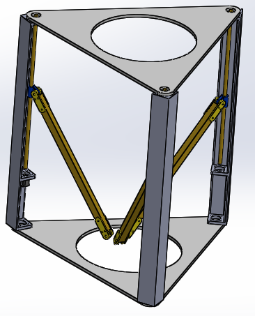
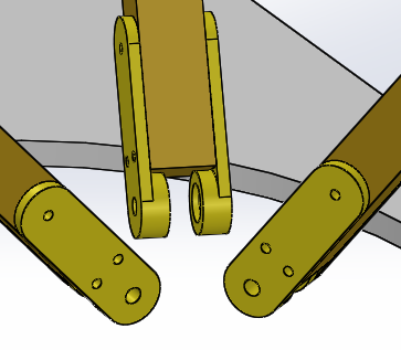
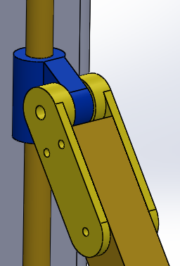
@A2: I think we are talking different things. I will try to make a diagram. Can you make a diagram of your inline arms?
Hopefully you can see in the pictures the inline joints of the arms.
Everything in the picture is a hack, as I wanted a quick drawing to work out different concepts.
**********************************************************
Build envelope:
I thought that by shortening the lead screws you would save money, and retain the same build envelop size,
I don't think that is possible now.
Shortening the lead screw raises the stepper motor mounting location,
and brings the stepper motors inside the enclosure.
With the stepper motors inside the enclosure the off set pivot of the shoulder joint becomes obsolete.
This is because the support for the stepper motors is in the way of the arm from hanging vertically.
That's OK if you're using double shear joints with the arms inline, you just have to be aware of the limitations.
I don't have any intentions of building arms this long, this is just an exercise:
The arms are about 35.0” long, and I estimate it can reach about 24.0”.
With a 3.0' foot long lead screw I'm estimating that you only get about a 4.0” build height.
So you need to add back that foot you took off of the lead screw to achieve some build height
If you cut a hole in the bottom platen I estimate that you can increase the Z axis build height by about 10.0”
for a total of about 14.0” build height, but the X-Y build envelope is reduced significantly.
This is because as you move down the arm needs to move out and away from the stepper motor mount.
In the picture the hole in the platen is 20.0” in diameter.
The takeaway for me with this exercise is that deltas are not good for making long X-Y length parts.
There appears to be an optimum/limiting size for a delta be efficient in the X-Y axis.
It looks like you need something like ~2X the length of the arms for the Z axis.
You're left with going up in the Z axis for maximum efficiency with a delta format (as you have mentioned in earlier post).
So what should the length of the arms be for a large delta?
@uncle_bob,
Quote
uncle_bob
Right now my *guess* on the mount is a printed part. The bearing is captive horizontally, but free vertically.
You gave me an idea with your bearing mount description.
Print a bearing holder with a flange with wide slots in the flange for the screws that anchor the bearing holder to the platen.
The bore in the platen is over sized relative to the printed bearing holder.
This will allow you to manually adjust the lead screw to get it parallel, and square.
You don't have to precision machine the platen, but you do need a precision hand tool to get the lead screw aligned correctly.
Quote
uncle_bob
With high torque motors and no flat on the shaft, I’m not real sure that a printed part is going to get the job done.
I’m guessing that epoxy will do fine for attaching one of the bronze nuts to the bottom of the shaft.
A small flat ground on the stepper motor shaft is what I'm going to try.
I'll use tape to cover the stepper motor bearings to prevent metal dust from mucking it up.
Edited 2 time(s). Last edit at 01/09/2014 04:59AM by A2.
|
Re: LISA Simpson January 09, 2014 07:49AM |
Registered: 10 years ago Posts: 1,433 |
Flat on shaft:
One thing you see a *lot* of warnings about on motor data sheets is - "do not machine the shaft, you will damage the bearings". You could indeed pull the motors apart and then do the machining. That probably also voids the warranty. Apparently keeping everything happy magnetically as you do this can be a problem. Even with the flats, there's still a bit of torque involved. There's also a range of shaft diameters. I'm not real sure that a 5mm shaft with a small flat is that much better than a round 8mm. A printed part is only just so strong. As soon as it'a a metal coupler I'm back to the lathe.
X-Y Delta:
Shaft based Delta printers all seem to wind up as tall / skinny designs. I suspect that you would need some sort of compound arms to get around that. (No, I don't actually know how to make that work). Another subtle issue is that delta's print big circles / small squares. A cartesian machine prints a big square / small circle. If your target gizmos are big squares you go one way. If your target "stuff" is roundish you might go another way.
|
Re: LISA Simpson January 09, 2014 11:14AM |
Registered: 10 years ago Posts: 10 |
|
Re: LISA Simpson January 09, 2014 12:10PM |
Registered: 10 years ago Posts: 1,433 |
I've never understood if the main concern is "crud" or if it's straight impact damage due to the induced vibration. Since the gizmo is magnetic, it will grab on to any bit of this or that. Of course that's true if you bolt one to a CNC as well. I do believe I've seen at least one being used on a CNC...(in say the last 5 minutes).
|
Re: LISA Simpson January 09, 2014 02:26PM |
Registered: 10 years ago Posts: 1,381 |
Quote
uncle_bob
Another subtle issue is that delta's print big circles / small squares. A cartesian machine prints a big square / small circle. If your target gizmos are big squares you go one way. If your target "stuff" is roundish you might go another way.
Bot types:
Cartesian.
Articulated arm (robot).
Delta.
Polar.
Hybrid (combination).
It would be useful if a new type of motion was invented.
The reason I'm studying delta printers is because I need to produce very round prototypes.
I'm hoping that I can get a surface finish, and dimensional accuracy suited to make cold casting molds from the prototype.
Quote
uncle_bob
I've never understood if the main concern is "crud" or if it's straight impact damage due to the induced vibration. Since the gizmo is magnetic, it will grab on to any bit of this or that. Of course that's true if you bolt one to a CNC as well. I do believe I've seen at least one being used on a CNC...(in say the last 5 minutes).
With hobby CNC routers you will find exposed stepper motors.
If you look at industrial equipment the entire motor or ends are typically sealed or at minimum covered.
The shields on bearings can be assembled incorrectly, have defects, or are of poor quality.
If you're hand grinding a small flat, it's precautionary to cover the bearings, and to prevent heat from migrating into the bearings.
If you're milling the shaft, the mill will hammer the harden ball bearings into the soft metal of the shaft creating indentations.
The bearings and indentations in the rotating shaft create a mini hammer mill of sorts, which will eventually self destruct it's self.
I watched an online video of this tech tip, very useful.Quote
CTF
Using kids putty to mask the insides of the steppers and the output of the shaft works very well to prevent dust.
Edited 2 time(s). Last edit at 01/09/2014 05:10PM by A2.


Sorry, only registered users may post in this forum.