LISA Simpson
Posted by nicholas.seward
|
Re: LISA Simpson January 09, 2014 04:45PM |
Registered: 12 years ago Posts: 85 |
|
Re: LISA Simpson January 09, 2014 04:54PM |
Registered: 11 years ago Posts: 979 |
IMO clamping on a M8 shaft will be more than enough. If all you have is a block of aluminum, band saw, and drill press then you can make a pretty decent coupler. Additionally there a few compounds that are meant to lock the shaft and the coupler together. I don't use them because with a prototype you never know what you have to change in the future. Keep in mind that the torque requirements are actually not that high. The size of the screws is for rigidity. (I am referencing the mega LISA talk.)
|
Re: LISA Simpson January 09, 2014 05:09PM |
Registered: 10 years ago Posts: 1,433 |
Solder:
I do a lot of soldering. You need to get the metal good and hot for the stuff to stick properly. Simple contact with the hot metal is not enough to give you a good joint. The temperatures involved are well above where the motor starts to get bothered.
Torque:
My main concern on torque is for acceleration and deceleration. I agree that the "smooth running" torque is quite low, even on a 2X LISA. Since most of the time in any move is either speeding up or slowing down, those speeds eventually do matter.
Clamp:
A two piece clamp (as opposed to a bushing) could indeed be made pretty easily. It would take a bit of modeling to see how well it fits inside the bolt pattern of the motor (using front facing bolts...). The whole lathe digression is indeed constructing excuse for a lathe not a need for a lathe.
Other motions:
There are a *lot* of other approaches to moving a gizmo around. Rotary build table with z lift is one that you don't see very often....
Edited 2 time(s). Last edit at 01/09/2014 05:57PM by uncle_bob.
|
Re: LISA Simpson first print club January 09, 2014 06:51PM |
Registered: 10 years ago Posts: 47 |
Sign me up for the first print club. It took me a while to learn Python and the procedure for converting the code, But actually it's quite simple. I'll try to make a video of the whole procedure to help out others.
Initially I had problems with the printer cupping similar to the deltas but I believe it was just a corrupt configuration -H file .
I'm hoping after several other builds are completed we can start working on additional coding for the end stops and more.
The 7/16 screws are quite stable ,however I do notice a little bit of backlash which I have to control somehow.
first print
|
Re: LISA Simpson first print club January 09, 2014 07:05PM |
Registered: 11 years ago Posts: 979 |
Congrats!!!! I should be able to get around to adding in some leveling code into segmentize within a week or two. I just did it on GUS so it shouldn't be that hard to convert it over. The idea is you find several sets of machine coordinates where you have a paper width between the nozzle and the glass. All you do is put those coordinates into the program and it will actually optimize your parameters. A leveling probe would be nice but LISA should hold a configuration for many prints. I found myself only releveling after I disassembled and reassembled.
|
Re: LISA Simpson January 09, 2014 07:06PM |
Registered: 10 years ago Posts: 1,433 |

|
Re: LISA Simpson January 09, 2014 07:12PM |
Registered: 11 years ago Posts: 979 |
@uncle_bob: ROTFLMAO. I have to give it to Roton. The screws aren't getting bent in transit. If I was near a shop I would have used a bandsaw myself. Instead I was holding the tube in one hand, a screwdriver in the other, and crying because my new toy was unreachable. Eventually I borrowed my way in. I bet Danny has a much smarter way. :-)
|
Re: LISA Simpson January 09, 2014 07:47PM |
Registered: 10 years ago Posts: 1,433 |
I've gotten a lot of stuff like this in the same sort of tubes. These guys are the first ones I've seen that put them together so you can't just pull them apart.
.............
Well the screwdriver and a modest amount of blood got it open.....
The nuts all work with the screws. There's a bit more play than I'd expected. Without putting a dial indicator on it I'm guessing. I'd say the nuts have got 0.015" of axial play and 0.007" of radial play. The longer plastic nut tips a bit less in degrees due to it's greater length.
They all spin nicely and the shafts are all in good shape. They do seem to weigh just about what they should.... heavy ....
Edited 2 time(s). Last edit at 01/09/2014 07:51PM by uncle_bob.
|
Re: LISA Simpson January 09, 2014 08:39PM |
Registered: 10 years ago Posts: 1,381 |

|
Re: LISA Simpson January 09, 2014 08:46PM |
Registered: 10 years ago Posts: 1,433 |
With one of these, getting the "real" numbers into the correction code is going to be vital. The errors you see are not all going to be "X is to long, change steps on X" sort of errors. I suspect it will take some time to get it all dialed in.
I would *guess* that printing a flat plate would be one of the first things to do and check. Check it for uniform thickness and get that dialed in first.
-------
Why does the family room now smell like an oily machine shop ....
I would *guess* that printing a flat plate would be one of the first things to do and check. Check it for uniform thickness and get that dialed in first.
-------
Why does the family room now smell like an oily machine shop ....
|
Re: LISA Simpson January 09, 2014 09:03PM |
Registered: 10 years ago Posts: 1,381 |
Quote
uncle_bob
With one of these, getting the "real" numbers into the correction code is going to be vital.
The errors you see are not all going to be "X is to long, change steps on X" sort of errors.
I suspect it will take some time to get it all dialed in.
Tks for the heads up I didn't realize that.
Quote
uncle_bob
Why does the family room now smell like an oily machine shop ....
lol, the sweet smell of manufacturing!
|
Re: LISA Simpson January 09, 2014 09:58PM |
Registered: 10 years ago Posts: 1,433 |
Floating Work Plate:
No I have not really worked out all the details on this, but ...
Rather than putting the work plate up on springs and bolts, why not use gravity? Hang the work plate below the mid plate. No crazy 900 lb springs. Gravity is fairly reliable. Suspend the work plate on three screws. Tweak them as needed to do first order leveling.
I suspect the sunken work plate idea will be a bit less popular with hot ends that have fans on them ....
Bearings on drive shafts:
The nutty metric dimensioned 3/4" bearings fit ok on the shafts. They have less radial play than the nuts. With something thin, you could shim them to be a tight fit.
Edited 1 time(s). Last edit at 01/09/2014 10:09PM by uncle_bob.
|
Re: LISA Simpson January 09, 2014 10:22PM |
Registered: 11 years ago Posts: 979 |

|
Re: LISA Simpson January 10, 2014 07:40AM |
Registered: 10 years ago Posts: 1,433 |
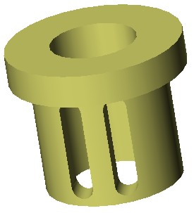
After playing a bit more with the nuts, one of the things that does indeed need to scale on a larger printer is the "stuff" on the shaft that reduces backlash and tip. I see three basic routes, each with a bunch of sub routes:
1) Use the flanged plastic nut and a longer printed structure. (Scale up the base design).
2) Run a pair of plastic nuts back to back. Space the second drive nut down the shaft with nuts on the three mounting bolts that go through the mounting flanges on the drive bolts.
3) Redesign either one to use the bronze nuts.
The plate drawings I did earlier are set up to allow any of the above. I might gain a fraction of an inch by ruling out the bronze nuts. The appeal of the bronze nuts is that they should last for a while.Whether the combination of plastic and steel works for 16 years and the bronze steel combo works for 18 years (or 15) - not real clear to me. I'm guessing that with the plastic, the steel lasts forever. With bronze the nuts last longer and the steel wears more. The only real data point I have is the M5 nuts and rods on an I3. They are *very* different beasts. The i3 parts do indeed wear in this kind of service. On a LISA there's a lot more motion than the Z axis of an i3.
Unless there is a "well known reason" to go with the bronze. The plastic is a lot less hassle. I'll need to do some measurements to really know if either one has an advantage in terms of tolerances.
------------------------
The bulk aluminum tube and bar stock came in today. UPS delivered it in a pile on the front porch. It was all there. Kind of amazing it arrived without much of a package around it all ....
Edited 6 time(s). Last edit at 01/10/2014 07:12PM by uncle_bob.
|
Re: LISA Simpson January 10, 2014 07:13PM |
Registered: 10 years ago Posts: 47 |
@A2
Yes, I calibrated It, the steps per mm were exactly the same as the equation.
.200*16 steps/rotation
25.4mm/rotation
200*16/25.4=125.98425196850393700787401574803 steps/mm
The cube printed out relatively well as you can see from the photos, the dimensions were close although there is a small deformity as you can see in the photos.
The cylinder on the other hand printed as expected , and is nowhere close to a cylinder.
As far as the printer goes it still is not totally tuned up ,there's a fair bit of backlash on the 7/16 screws and some of the joints need a little attention. But I think this was good demonstration for out of the gate.
test ring
20mm test cube
20mm test cube
20mm test cube
|
Re: LISA Simpson January 10, 2014 08:27PM |
Registered: 10 years ago Posts: 1,381 |
Tks for taking the time to show what Lisa is capable of, while not totally tuned up!
The difference between the length of the sides are ~1.0 mm.
The Z axis is +0.74 mm.
Looking forward to the time when you have it dialed in!
I was under the impression that a delta printer would make parts more circular,
and with greater precision than a Cartesian printer.
I'm new to this, please explain why you didn't expect a circular part?
Many thanks for offering instructions on how to install the software, I'm looking forward to watching your video!
Quote
Dannydefe
there is a small deformity as you can see in the photos.
The difference between the length of the sides are ~1.0 mm.
The Z axis is +0.74 mm.
Looking forward to the time when you have it dialed in!
Quote
Dannydefe
The cylinder on the other hand printed as expected , and is nowhere close to a cylinder.
I was under the impression that a delta printer would make parts more circular,
and with greater precision than a Cartesian printer.
I'm new to this, please explain why you didn't expect a circular part?
Quote
Dannydefe
It took me a while to learn Python and the procedure for converting the code, But actually it's quite simple.
I'll try to make a video of the whole procedure to help out others.
Many thanks for offering instructions on how to install the software, I'm looking forward to watching your video!
|
Re: LISA Simpson January 10, 2014 08:59PM |
Registered: 10 years ago Posts: 1,381 |
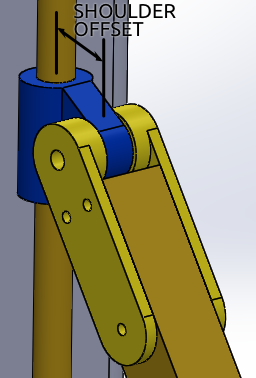
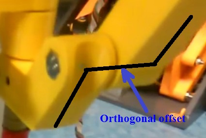
Definitions:
Offset = a radial displacement from the lead screw axis.
Orthogonal-offset = single shear joint.
Centered, (inline) = double shear joint.
OK, we are talking about two different things, now I see what you're calling an offset, tks!
Looking at the arms of Simpson I see that the orthogonal offset of the arm at
the shoulder is re-centered at the end effector with an orthogonal offset hub connector.
It looks like there are no variables for an orthogonal offset in the g-code preprocessor,
as it's not required if the arms are readjusted to be centered, (inline).
So arms that are centered, (inline) as I have drawn don't require any special math, correct?
Tks.
Edited 2 time(s). Last edit at 01/10/2014 09:00PM by A2.
Offset = a radial displacement from the lead screw axis.
Orthogonal-offset = single shear joint.
Centered, (inline) = double shear joint.

OK, we are talking about two different things, now I see what you're calling an offset, tks!
Looking at the arms of Simpson I see that the orthogonal offset of the arm at
the shoulder is re-centered at the end effector with an orthogonal offset hub connector.
It looks like there are no variables for an orthogonal offset in the g-code preprocessor,
as it's not required if the arms are readjusted to be centered, (inline).
So arms that are centered, (inline) as I have drawn don't require any special math, correct?
Tks.
Edited 2 time(s). Last edit at 01/10/2014 09:00PM by A2.
|
Re: LISA Simpson January 10, 2014 09:51PM |
Registered: 11 years ago Posts: 979 |
|
Re: LISA Simpson January 10, 2014 10:36PM |
Registered: 10 years ago Posts: 1,433 |
Circular objects:
If you take a look at the picture of the printed ring, it's got three lobes on it. You have three drive screws / 3 arms / 3 hub arms .... Think of it as many chances for things to stretch or shrink along each of the 3 drive axis. You still have distortion it's just not directly in X, Y, and Z. Moving the tool in a circle is just as difficult as moving it in pure X, Y, or Z. There is no useful motion that you can execute moving only one shaft.
Backlash:
I'm wondering if the backlash goes up as the screws get bigger. It seems like a reasonable assumption. The anti-backlash may need to be more than scaled on a large printer....
|
Re: LISA Simpson January 10, 2014 11:08PM |
Registered: 10 years ago Posts: 1,381 |
Quote
uncle_bob
Backlash:
I'm wondering if the backlash goes up as the screws get bigger.
It seems like a reasonable assumption.
The anti-backlash may need to be more than scaled on a large printer....
As you know Roton High lead thread profile is propitiatory,
generally yes the clearances increase as the diameter grows.

A trick to take up backlash in a nut:
Push with a set screw a piece of Nylon rod into the thread profile.
Drill a hole into the side of the nut preferably at the crest of the thread in the nut.
Slowly heat the Nylon up, and press it into the thread profile,
repeat until it's a perfect match.
Remove the Nylon stud after each forming step to remove the flash.
This will require periodic adjustment.
Edited 2 time(s). Last edit at 01/10/2014 11:10PM by A2.
|
Re: LISA Simpson January 11, 2014 08:56AM |
Registered: 10 years ago Posts: 1,433 |
The weight of the system goes up as it gets bigger. There's enough weight on the nuts to seat them pretty well in the threads. Since the weight is sort of a cube thing (ignoring going to aluminum or cedar), the self correction will scale up.
The tapping and set screw approach probably is more practical with the bronze nuts than with the nylon ones. With the nylon you probably need to tap both the nut and the printed structure that goes over the nut.
I suspect this is going to be a bit of "try it and see"....
The tapping and set screw approach probably is more practical with the bronze nuts than with the nylon ones. With the nylon you probably need to tap both the nut and the printed structure that goes over the nut.
I suspect this is going to be a bit of "try it and see"....
|
Re: LISA Simpson January 11, 2014 01:17PM |
Registered: 10 years ago Posts: 1,433 |
Backlash:
Seems like there is a simple / high cost solution to the problem. Set up the flanged nuts back to back with the bolts as previously described. Instead of spacing them with nuts and doing a lot of fiddling, put a fairly solid spring on each of the bolts. The pressure required to zero them out is not all that great. A finger squeeze between the flanges will get the play down to the point you can't wiggle them anymore. The same squeeze trick works with the bronze nuts. They zero out with a bit less finger pressure. Both still rotate quite smoothly when zeroed out.
I'll probably wear out the nuts eventually doing this. My guess is that the force is not great enough for that to be a limit on the printer's life cycle.
Yes feel free to come back in a month or two and ask me how good an idea it was once I've had to put three of them together .... Compressing the three springs and lining everything up all at one time could be "interesting". A single much larger spring between the flanges might be easier to assemble. You would likely need a printed part to captivate it. The way I see it, the bolts need to go through from the bottom of the assembly so the lower nut is free to slide on an un-threaded portion of the bolt. You also need a bolt that has threads starting by the time it gets to the flange in the upper nut. Off to McMaster Carr land .... The standard jobber specs on machine screws aren't detailed enough to be sure of getting the right parts. Looks like a trip to the hardware store is the next step.
Edited 1 time(s). Last edit at 01/11/2014 02:07PM by uncle_bob.
|
Re: LISA Simpson January 11, 2014 02:06PM |
Registered: 10 years ago Posts: 1,381 |
@uncle_bob:
Another idea, cut slots into the nut, then use a hose clamp to squeeze the thin section into the lead screw threads.
Place a small wedge under the hose clamp over the thin section to help push only that section into the lead screw.
Edited 1 time(s). Last edit at 01/11/2014 02:06PM by A2.

Another idea, cut slots into the nut, then use a hose clamp to squeeze the thin section into the lead screw threads.
Place a small wedge under the hose clamp over the thin section to help push only that section into the lead screw.
Edited 1 time(s). Last edit at 01/11/2014 02:06PM by A2.
|
Re: LISA Simpson January 11, 2014 02:24PM |
Registered: 10 years ago Posts: 1,433 |
I *think* I want to have the arm take off from as close to the un-flanged end of the nut as possible. That would give me the max usable length on the drive screw. Given that this is a 5' screw I may be over thinking a bit here. If the takeoff is on that end, playing with the flanged nut is going to be a bit involved. The arm joint will take up at least 1" of the nut and more likely 1.5". There is 1.724" of smooth outer wall on the nut before it hits either the flange or tapers at the un-flanged end. There's not as much room there as you might think.
A few more numbers and a little more complication: The bore is through the threads is 0.638" . The three mounting holes holes in the flange are 0.205" diameter. The flange is maybe 0.315" wide. A standard #10 socket head cap screw has a head that's 0.312" dia. You can (barely) get a #10 cap screw above the flange. A #10 hex nut at 3/8" - not going to happen without machining the flange.
If I do go with the double nut idea, I may print an intermediate part to tie everything together. Given the dimensions I have on the plate, the whole spring and bolt assembly could go completely outside the flanges on the nuts..
-------------------
Looks like:
[www.mcmaster.com]
Will give me (gulp) 18 pounds of force between the flanged nuts. It also has some smaller siblings that are a bit less aggressive. Since there is weight on the upper nut, I'll need a reasonable amount of force simply to keep things spread apart. Yes I could sacrifice 3" of build height and let gravity work for me.
They also have some large diameter stuff if I want to put a couple hundred pounds of force between the nuts.
------------------
You *could* put the nut below the whole arm mount "stuff". That way there's pretty much no conflict between what ever you do to the nut and the mount.
Edited 6 time(s). Last edit at 01/11/2014 06:23PM by uncle_bob.
|
Re: LISA Simpson January 12, 2014 04:04AM |
Registered: 12 years ago Posts: 85 |
Would CNC world parts work for us here? [www.cncrouterparts.com]
|
Re: LISA Simpson January 12, 2014 09:53AM |
Registered: 10 years ago Posts: 1,433 |
Parts like the CNC site listed would indeed work for the stepper to drive shaft *if* I wasn't working with such odd diameters. Going from 3/4" to 8mm is not common enough to be a stocked (or even an optional) item for any of the guys I have found.
----------------
Parts are beginning to pile up in odd corners around the house. As I move them from corner to corner .. they are heavy. I probably should start adding up all of the weights. Using bar stock for the arms may get crossed off the list once I do. (they add about 10 lb to the total). Swapping them out for a hub mounted extruder sounds like a better use of that part of the weight budget.
The plastic drive nuts are rated at 1,400 lb each. My guess is that the floor loading will be an issue before they are even if I cut away part of them.
|
Re: LISA Simpson January 13, 2014 06:41PM |
Registered: 10 years ago Posts: 1,433 |
The 18+" aluminum disk came in today. A 34+ lb lump of aluminum is ... heavy.
[www.ebay.com]
The surface finish is quite good. There's a bit of dirt and a minor scratch here and there. The streaks in the picture are just dirt. I'd say it's as good a printing surface as anything else out there. I'm not sure how well it would stand up to having plastic scraped off of it with a paint scraper. Other than that it's as good as a piece of glass. The edge finish is ok. It's better than a bandsaw cut. Not quite what I'd put on it with a CNC. It's nothing that would impair it's use for a printing surface. It's just not quite as pretty as the mirror finish on the top and bottom of the plate.
|
Re: LISA Simpson January 13, 2014 07:36PM |
Registered: 10 years ago Posts: 1,381 |
@uncle_bob:
If you want a mirror finish on your aluminum Flitz Metal Polish is probably all you need.
I would begin and end using a wax, and grease remover.
Flitz Industrial Strength Aluminum PreClean, removes heavy oxide (soak for 20 seconds, buff off).
Flitz Metal Polish, Fiberglass & Paint Restorer + buffing wheel.
Flitz polish ( diluted version) + buffing wheel.
Finish with a wax and grease remover, (automotive paint supplier, bug & tar remover).
|
Re: LISA Simpson January 13, 2014 09:26PM |
Registered: 10 years ago Posts: 1,433 |
At this point I'm not to concerned about mirror finish as much as I'm concerned about keeping the surface flat. I'll probably keep it in the packaging until I'm ready to mount it and give it a good soap and water scrub then. If I can't pick a "good side" once I get the dirt all off of it, I'll probably go shopping for some Flitz.
Thanks!
Thanks!
|
Re: LISA Simpson January 13, 2014 11:08PM |
Registered: 10 years ago Posts: 1,381 |
Alcoa Mic-6 looks like a very stable metal at high temperatures.
Are you planning on printing directly onto the aluminum plate?
How flat of a surface do you require?
You could use a lapping plate to get it flatter.
You might be able to get away with adhesive backed wet/dry sand paper.
I have a pair of cast iron lapping blocks for steel, but it's not recommended for aluminum.
For lapping various grades of aluminum metal the Garnet and
Silicon Carbide compounds are recommended.
[www.us-products.com]
[americanlap.com]
Alcoa Mic-6
Cast Plate allows high-speed metal removal with little, if any,
of the distortion commonly inherent in long grained wrought, flat-rolled metals.
Flatness tolerance is maintained within .005" on 3/4"- 4" thickness.
Thermal Cycling can be performed up to 800° F under controlled conditions.
[www.alcoa.com]


Sorry, only registered users may post in this forum.