LISA Simpson
Posted by nicholas.seward
|
Re: LISA Simpson December 21, 2013 01:11PM |
Registered: 10 years ago Posts: 1,381 |
Heated Enclosure:
I plan to use translucent acrylic for the side panels, and for it's insulative value.
All electronics less the extruder stepper motor feeding the filament will be
located outside the heated enclosure.
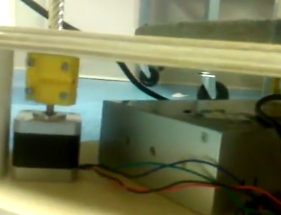
Here you can see that Lisa stepper motors are located outside,
and below the enclosure, same with the electronics:
I'm going to heat the enclosure like a laboratory convection oven.
A squirrel cage or CPU fans will evenly circulate warm air.
If it helps, I'll also direct warm air into the center of large hollow body objects.
If warranted, the extruder stepper motor will have a heat exchanger harvested
from a laptop CPU bolted to it with CPU thermal compound.
If the heat is too high for the extruder stepper motor, I'll place the heat exchanger
in a closed-circuit corrugated tube, and circulate cool air past the heat exchanger.
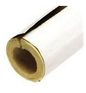
If warming of the filament turns out to be an issue, I'll run the filament in an insulative sleeve,
the type that is commonly used on warm water piping.
Edited 2 time(s). Last edit at 12/21/2013 01:16PM by A2.
I plan to use translucent acrylic for the side panels, and for it's insulative value.
All electronics less the extruder stepper motor feeding the filament will be
located outside the heated enclosure.
Here you can see that Lisa stepper motors are located outside,
and below the enclosure, same with the electronics:


I'm going to heat the enclosure like a laboratory convection oven.
A squirrel cage or CPU fans will evenly circulate warm air.
If it helps, I'll also direct warm air into the center of large hollow body objects.

If warranted, the extruder stepper motor will have a heat exchanger harvested
from a laptop CPU bolted to it with CPU thermal compound.

If the heat is too high for the extruder stepper motor, I'll place the heat exchanger
in a closed-circuit corrugated tube, and circulate cool air past the heat exchanger.
If warming of the filament turns out to be an issue, I'll run the filament in an insulative sleeve,
the type that is commonly used on warm water piping.

Edited 2 time(s). Last edit at 12/21/2013 01:16PM by A2.
Attachments:
open | download - ScreenHunter_328 Dec. 21 12.34.jpg (47.6 KB)
open | download - ScreenHunter_329 Dec. 21 12.46.jpg (28.3 KB)
open | download - ScreenHunter_330 Dec. 21 13.02.jpg (30.3 KB)
open | download - ScreenHunter_331 Dec. 21 13.04.jpg (24.7 KB)
open | download - ScreenHunter_332 Dec. 21 13.11.jpg (5.2 KB)
|
Re: LISA Simpson December 21, 2013 01:43PM |
Registered: 10 years ago Posts: 100 |
Of course, you will not want to have any PLA printed parts inside the heated enclosure. 
Aluminum machined parts would work.
I would think it better to have a movable air "lid" that the extruder pokes through (two layers of fanfold papers in opposite directions with long slit in the middle sort of idea -- though that one is patented).
Then keep everything but the bottom of the extruder and the print outside of the heated area. This might be much easier to accomplish on a Wally design.
|
Re: LISA Simpson December 21, 2013 02:27PM |
Registered: 10 years ago Posts: 1,381 |
@see3d
I will be using Nylon printed parts.
What you are attempting to describe, fan fold paper?

edit:
I think I understand, place a tube (an enclosure inside the enclosure ) around the extruder such that the warm air
inside the enclosure is not able to warm it up.
The tube projects through the top of the enclosure, through a diaphragm that has a slit in it to allow the tube to freely move around.
The problem with that idea for this application, is the tube moves all over the place, one slit wouldn't be enough.
You could use a collapsible/flexible tube enclosure, with a helper spring to hold it up and out of the way,
with a single stationary hole for the tube, that would work.
Edited 1 time(s). Last edit at 12/21/2013 02:36PM by A2.
I will be using Nylon printed parts.
What you are attempting to describe, fan fold paper?
edit:
I think I understand, place a tube (an enclosure inside the enclosure
) around the extruder such that the warm air inside the enclosure is not able to warm it up.
The tube projects through the top of the enclosure, through a diaphragm that has a slit in it to allow the tube to freely move around.
The problem with that idea for this application, is the tube moves all over the place, one slit wouldn't be enough.
You could use a collapsible/flexible tube enclosure, with a helper spring to hold it up and out of the way,
with a single stationary hole for the tube, that would work.
Edited 1 time(s). Last edit at 12/21/2013 02:36PM by A2.
|
Re: LISA Simpson December 21, 2013 03:09PM |
Registered: 10 years ago Posts: 100 |
|
Re: LISA Simpson December 21, 2013 05:58PM |
Registered: 10 years ago Posts: 1,433 |
Getting the heat exchangers to mate up with a stepper on the extruder may be a bit fun. They sort of expect the heat to depart in all directions. Put another way, they don't design them with a good heat transfer surface. I think a Bowden tube setup with an extruder outside the enclosure would be the better approach.
How hot do you think the enclosure needs to be?
How hot do you think the enclosure needs to be?
|
Re: LISA Simpson December 21, 2013 06:17PM |
Registered: 10 years ago Posts: 1,381 |
@uncle_bob
New territory for me, so I look to injection molding parameters of PP/PE.
To reduce warping the mold will open when the parts cool to ~130F (54 C).
So that is one temperature that I'm keeping in mind.
This puts us at the max temperature for the extruder stepper motor (50 C).
The stepper motors for the arms are out side of the heated enclosure, so they are a non issue.
So you only need to manage the heat for the extruder motor which I think you can do.
If you're planning on using PLA components, you might run into creep issues.
Edited 1 time(s). Last edit at 12/21/2013 06:21PM by A2.
New territory for me, so I look to injection molding parameters of PP/PE.
To reduce warping the mold will open when the parts cool to ~130F (54 C).
So that is one temperature that I'm keeping in mind.
This puts us at the max temperature for the extruder stepper motor (50 C).
The stepper motors for the arms are out side of the heated enclosure, so they are a non issue.
So you only need to manage the heat for the extruder motor which I think you can do.
If you're planning on using PLA components, you might run into creep issues.
[forums.reprap.org]Quote
nophead
PLA softens ~50C, melts at ~ 160C, extrudes and bonds well at 180C-190C.
Edited 1 time(s). Last edit at 12/21/2013 06:21PM by A2.
|
Re: LISA Simpson December 21, 2013 07:48PM |
Registered: 10 years ago Posts: 1,433 |
|
Re: LISA Simpson December 21, 2013 08:11PM |
Registered: 10 years ago Posts: 1,381 |
|
Re: LISA Simpson December 21, 2013 09:43PM |
Registered: 10 years ago Posts: 47 |
I posted a video of some of the first rough moves on my build.
It's just barely assembled, a lot of the components are loose. Now I have to sit down and work out the tuning and geometry measurements properly. I think the 7/16 screws are really going to do a great job, they really seem quite stiff.
first moves
Edited 1 time(s). Last edit at 12/21/2013 10:54PM by Dannydefe.
|
Re: LISA Simpson December 21, 2013 09:46PM |
Registered: 10 years ago Posts: 1,381 |
|
Re: LISA Simpson December 21, 2013 10:26PM |
Registered: 10 years ago Posts: 1,433 |
|
Re: LISA Simpson December 21, 2013 11:28PM |
Registered: 10 years ago Posts: 1,381 |
@Dannydefe
The carbon fiber columns look great!
Why are the columns interior white, did you leave the peel ply on?
Print some feet for the columns, you don't want to chip those pretty columns.
Looks like you're using an aluminum coupler between the stepper motor and lead screw, custom, or store bought?
The arm nut, and the upper screw clamps are black, what's the story behind them?
|
Re: LISA Simpson December 21, 2013 11:36PM |
Registered: 10 years ago Posts: 1,433 |
|
Re: LISA Simpson December 22, 2013 08:33PM |
Registered: 10 years ago Posts: 47 |

|
Re: LISA Simpson December 23, 2013 09:46PM |
Registered: 10 years ago Posts: 1,433 |
Despite the best efforts of UPS to loose the package, the steppers got here today. Short quick evaluation - I'm impressed.
1) The break out board that goes to the LPT port on a PC (that I dismissed as useless early on) is quite complex. It appears to be opto isolated !!
2) The controllers seem to be well made and they can be mounted easily.
3) The motors are massive .... big heavy tall things (yes they are the same ones in the picture and no taller than they show on the spec sheet).
The detent torque on the motors is high enough that I suspect it will hold a fairly heavy print head up in the air with no power applied. They are at the "hard to turn with your fingers" level.
The motors are indeed round shaft / no flat as the drawings show.
Everything in the package is Wanti labeled. That goes for the ... 36V power supply as well. It's a MeanWell rip off supply. Part number is a S-350-36. That would suggest that a 350W supply is probably a good idea for one of these setups. It also suggests to me that the 50V rating on the controllers may be a bit optimistic. Not quite sure how / why I got the supply, I'll have to go back and look at the listing.
All connections are made via the same sort of screw down and plug in connectors used on the Ramps for the main supply input.
-----
Somehow the screws that were quite securely holding the top cover on managed to come loose .... I suspect my warranty is no longer valid.
The board inside is well made. It's conformably coated. The electrolytic caps are China product rather than Japanese. They show as being rated for 63V and 105C. That would suggest that the 50V may not be all that optimistic.
Power is via a switcher and then some linear regulation after that. The setup is opto's into a .... Atmel Mega ... into some logic and then a full discrete FET H bridge for each stepper. More or less, if the Mega on the Ramps can spit out pulses, I'd bet this thing can receive pulses. I doubt that the top end stepping speed on one is much higher than the top end speed on the other.
------
I haven't hooked them up yet. The family seems to have some sort of holiday plans for the next couple days. It may be a bit before I can fire them up. At this point I'm happy with them.
Edited 1 time(s). Last edit at 12/23/2013 09:47PM by uncle_bob.
|
Re: LISA Simpson December 23, 2013 10:34PM |
Registered: 10 years ago Posts: 17 |
|
Re: LISA Simpson December 24, 2013 12:09AM |
Registered: 10 years ago Posts: 1,381 |
|
Re: LISA Simpson December 24, 2013 08:48PM |
Registered: 10 years ago Posts: 1,433 |
The kit I bought was:
[www.ebay.com]
It's a USA ship version of a Wanti kit with three DQ542MA's, three NEMA-23 428 in-oz steppers, and a DB-25 break out board.
The seller is:
[myworld.ebay.com]
They have a number of similar kits with various shipping options.
Once the holiday stuff calms down I'll see what I can do about more information / pictures / what ever.
Edited 1 time(s). Last edit at 12/24/2013 08:49PM by uncle_bob.
|
Re: LISA Simpson December 25, 2013 12:06PM |
Registered: 10 years ago Posts: 2 |
instead of perfectly straight threaded rod, i think it would be helpful to have smooth rod to guide the movement of each arm and threaded rod to drive the movement, as seen on the prusa i3. this way, the threaded rod neednt be perfectly straight, allowing it to be purchased from ahardware like home depot here in america. their larger diameter smooth rods are also very straight and run $5-$6. their threaded rod is significantly cheaper though they are not metric, their metric values/parameters can be calculated or looked up.
|
Re: LISA Simpson December 25, 2013 01:05PM |
Registered: 11 years ago Posts: 979 |
@badetise:
There are a few issues to work out with your suggestion. First, you need the pitch of your screw to be 10mm or more so the speed isn't painfully slow. Second, the shoulder pivots on the rod in this design so you will have to get fancy if you want to drive with anything other than the rod itself. Both problems are solvable but do need to be addressed.
There are a few issues to work out with your suggestion. First, you need the pitch of your screw to be 10mm or more so the speed isn't painfully slow. Second, the shoulder pivots on the rod in this design so you will have to get fancy if you want to drive with anything other than the rod itself. Both problems are solvable but do need to be addressed.
|
Re: LISA Simpson December 26, 2013 01:18PM |
Registered: 10 years ago Posts: 1,433 |
Even with some big motors and drivers, I suspect that I will have some speed limits on a 1/2" (12.5 mm) pitch screw. That's with a direct drive setup. I can live with the speed I'll (hopefully) get. I would not be happy with what the calculations suggest I'd get on a 1/4" pitch screw.
Going to gears or belts to drive the screws would be one way to get around that limit. A 2:1 to 4:1 ratio would be fairly easy to do either way. Backlash is the first thing you would have to take care of. Doing that without adding complexity to the design would be a challenge.
As it is, "good" thread rods are not a lot more / may be less than the cost of a good (fat) smooth rod. Drive nuts do cost money, so do bearings for large diameter smooth rod.
The next issue I see is the binding up of the thread rod to the smooth rod. On long drive distances, having the end of the rod just flop around isn't very pretty. Confining it brings up the possibility of a pinch point somewhere in the travel.
|
Re: LISA Simpson December 26, 2013 01:47PM |
Registered: 10 years ago Posts: 10 |
First post here. This is all very exciting!
I was going to purchase a RockStock Max, but I think that I will go with the LISA now.
I probably will try to build the bigger version, about 20" diameter and 25" tall or so.
Thank you for sharing this amazing knowledge, this is quite impressive.
I just got a membership to Techshop and I am in the process of taking the classes. (www.techshop.com)
All these tools are pretty nice and will certainly help with some of the parts I need for this project.
|
Re: LISA Simpson December 26, 2013 02:17PM |
Registered: 10 years ago Posts: 1,381 |
@CTF,
What one do you mean?
20" diameter print envelope.
25" tall print envelope.
or
20" diameter machine outside dimensions.
25" tall machine outside dimensions.
Presently I'm contemplating a 3X factor of the original Lisa arm length.
200 mm x 3 = 600 mm, (Diameter 23.62” inches).
But a 2x factor might be large enough for my needs.
200 mm x 2 = 400 mm, (Diameter 15.75” inches).
If you plan to scale the original size, down load the Inventor files to learn exactly what the dimensions are.
These are all the files that you need to build a Lisa:
ConceptFORGE / LISA Simpson:
[github.com]
Marlin Firmware:
[github.com]
|
Re: LISA Simpson December 26, 2013 06:32PM |
Registered: 10 years ago Posts: 10 |
@A2,
I have no particular need for a specific size, I would like to build something simply a bit bigger than the original Lisa.
I think that the 20" diameter print envelope, 25" tall print envelope would be about right.
A little bit bigger, or smaller would be fine.
Since I am starting all this, I will likely follow the choice of one of the more experienced builders here.
23.62" print diameter sounds good.
As long as the budget does not strech too far past $1000, I think that i am OK.
Thank you for the links.
|
Re: LISA Simpson December 26, 2013 07:30PM |
Registered: 11 years ago Posts: 979 |
I know this is my design but I feel the need to reiterate that there are a lot of thing that could go wrong with a bigger design. Things don't always scale like you would hope them too. If you have a good engineering background and/or a medium/big budget to absorb mistakes then this is a project for you.
Leveling in general on any big build is always a problem.
For this design, twisting of the arms is a consideration so scale the arm dimensions with everything else.
The screw size and the backlash of the nuts are another big concern. I posted a formula somewhere on this thread but know that is what I consider the edge of acceptability.
Firmware doesn't currently exist for this. (I am sure we can modify marlin and get the autoleveling to work but this hasn't been done yet and will have to be done by one of us. I am happy with the software preprocessor so I will probably wait for others to tackle it.)
This is more but I hope I have given anyone wanting to build a mega LISA a moment of pause. $1000 may be just enough for a 2X version (I would budget more) but I am uncertain about for a 3X version. Expect mistakes and expect budget overruns. Don't get me wrong. I want mega LISAs to exist. I just don't want anyone to unintentionally jump into the deep end. Happy building!
|
Re: LISA Simpson December 26, 2013 07:54PM |
Registered: 10 years ago Posts: 10 |
@Nicholas,
First things first, THANK YOU for initiating this project.
I think that this is really interesting.
One thing that scares me a bit however is that you mention that there is no firmware...
While I used to do programming in a previous life, I have no experience whatsoever with firmware programming.
Are you saying that there is no way at this time to get this working with a downloadable file?
Last but not least, how would you compare the accuracy and resolution of the Lisa, with a size similar to the RockStock Max?
They claim a positioning accuracy of 0.02mm!
Edited 1 time(s). Last edit at 12/26/2013 07:54PM by CTF.
|
Re: LISA Simpson December 26, 2013 08:02PM |
Registered: 11 years ago Posts: 979 |
I am not sure what exactly the min xy resolution of LISA is but for my 1/32 microstepping with 1" pitch screws the z resolution is 4 microns. Relying on microstepping is a bit of a cheat but I am sure the RSMax doesn't have 20 micron resolution with microstepping.
I do have a workable preprocessor that will get you printing but I wouldn't trust a 2X or 3X machine without some kind of software/firmware leveling. I use to have a annoying to use software leveler built into the preprocessor for THOR Simpson but I ripped it out because it was annoying to use. If I get around to building a bigger LISA and leveling is an issue I may try to put it back in.
I do have a workable preprocessor that will get you printing but I wouldn't trust a 2X or 3X machine without some kind of software/firmware leveling. I use to have a annoying to use software leveler built into the preprocessor for THOR Simpson but I ripped it out because it was annoying to use. If I get around to building a bigger LISA and leveling is an issue I may try to put it back in.
|
Re: LISA Simpson December 26, 2013 08:05PM |
Registered: 10 years ago Posts: 10 |
|
Re: LISA Simpson December 26, 2013 09:28PM |
Registered: 11 years ago Posts: 979 |
|
Re: LISA Simpson December 27, 2013 03:23AM |
Registered: 10 years ago Posts: 10 |
Are the files on the Github repository the latest and current ones?
I believe they are, but wanted to confirm.
If I not mistaken, the Lisa original print dimensions are 235mm tall, with a MAX circle print area of about 200mm or a square with 156mm sides.
Is this correct?
I am ready to build this printer, and I am still debating whether I would be happy with the original size, or make it at least a 2X.
I will probably not need to go any bigger than that for now, after all this is my first printer build.
I must say I can probably build the printer mechanically without too many snags, but I am a bit concerned over the electronics/software side of things...
The software leveller requirements scares me the most. I would be completey unable to program this myself.
If the 2X machine is "useless" without it, then it is a show stopper for me for the 2X.
I may want to upgrade the stepper motors, so that the machine can be more versatile if I need to.
The ebay models listed in this thread seem a good option.
Last but not least, the Rockstock Max is on sale right now, at under $900.
Other than the obvious print size differences, which other factors make the Lisa or Lisa 2X a much better investment?
I want to make sure that I make the most of my budget. I know that if I build the RockStock Max for example, and realize that the Lisa is a much better printer overall, I will not have the budget to build another 3D printer for a while...
I am more concerned with print resolution/quality in PLA and ABS than print size.
Thank you for helping me make the right choices.


Sorry, only registered users may post in this forum.