Dual Extrusion Offset
Posted by Aberrant
|
Dual Extrusion Offset November 16, 2013 03:02PM |
Registered: 10 years ago Posts: 65 |
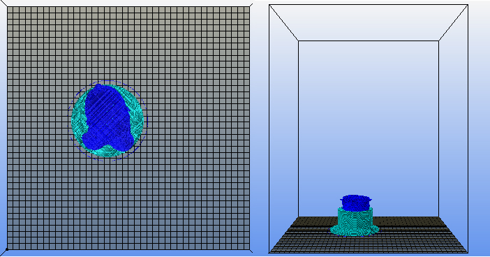
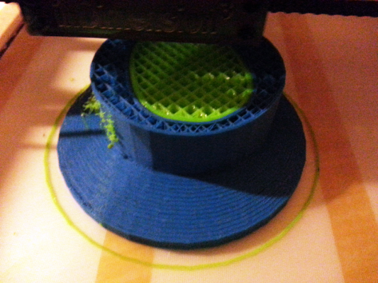
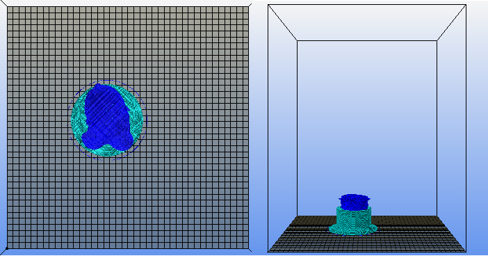
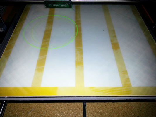
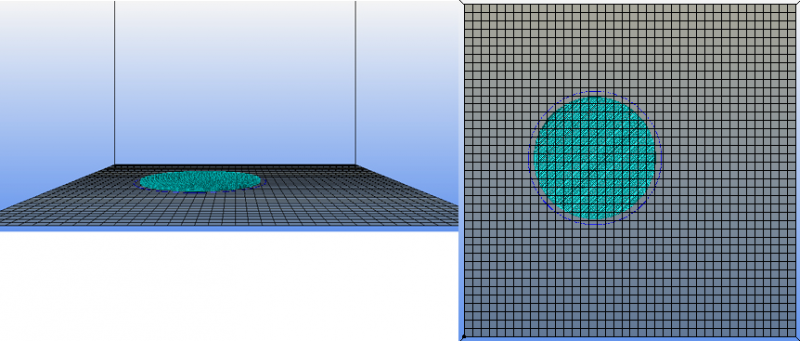
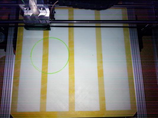
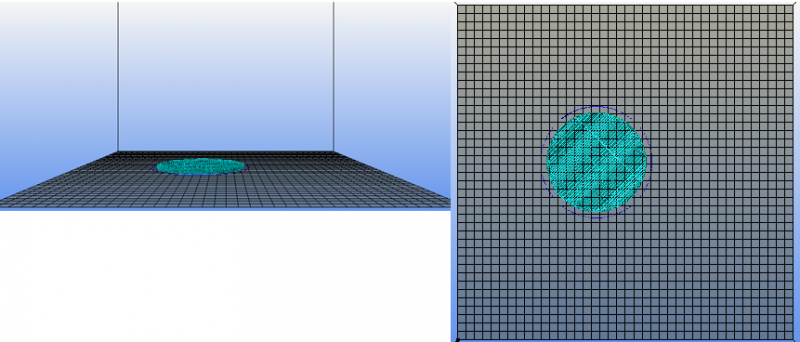
I set my X offset in the printer settings and I have done dual extrusion prints sucessfully before. While using the same workflow, I am now getting an offset when trying to print. The image attached shows what I mean. The blue circle is meant to be inside the green (Skirt) but instead it is offset.
|
Re: Dual Extrusion Offset November 19, 2013 01:34AM |
Registered: 10 years ago Posts: 65 |
I am getting better results than before, considering the circles were way off.
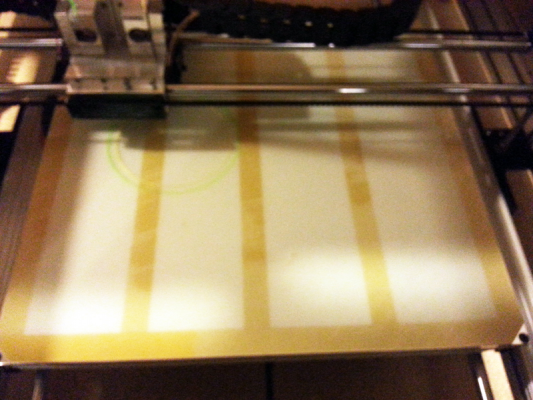
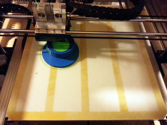
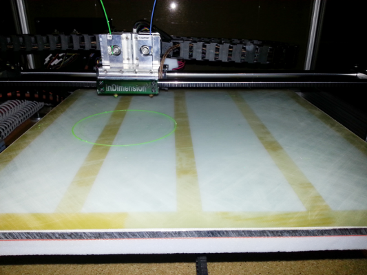
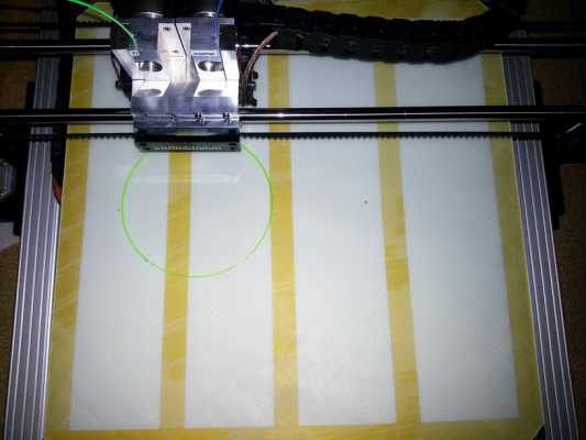
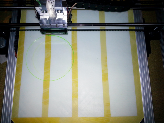
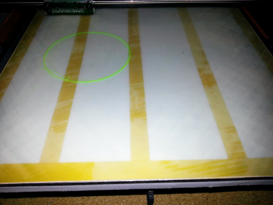
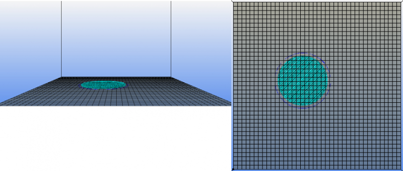
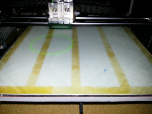
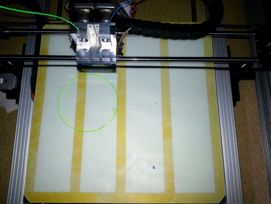
Now the issue is the placement. I see the g-code showing the head should be close to center. However, when it begins to lay the first layer of the support either the whole thing is offset. Take a look at the two attached images to see what I mean about the print being different than the g-code shows.
Now the issue is the placement. I see the g-code showing the head should be close to center. However, when it begins to lay the first layer of the support either the whole thing is offset. Take a look at the two attached images to see what I mean about the print being different than the g-code shows.
|
Re: Dual Extrusion Offset November 24, 2013 03:45AM |
Registered: 10 years ago Posts: 65 |
I switched the offset in slic3r to 0.0mm and set the M218 g-code. I get the same results with the print shifted to the left. I have the settings matching my print bed, and I have never had an issue like this. I cannot figure out why everything is not printed the way it looks in the g-code prview within Repetier Host.
|
Re: Dual Extrusion Offset November 24, 2013 06:27AM |
Registered: 10 years ago Posts: 40 |
You need to set the offsets with a G10 command not M218. The format of the G10 command is:-
G10 Pn Xn Yn Zn
Where:-
P is the number of the extruder (1st extruder is P0)
X is the x offset for this extruder
Y is the Y offset fopr this extruder
Z is the z offset, but (at least on my Reprap Pro Medel Tricolour) this is normally set to 0 as the z offset is set by the z limit switch.
Set your first extruder to all zeros (i.e G10 P0 X0 Y0 Z0)
then set the second one so that it prints in the correct place in relation to the first.
Don't forget to save the setting in firmware with M500 aftwerwards.
There is a very good description of this process at [www.reprappro.com]
Hope this helps
Harvey
|
Re: Dual Extrusion Offset November 24, 2013 12:02PM |
Registered: 13 years ago Posts: 2,947 |
Marlin says it is M218 [github.com]
But the RepRap wiki says it is G10 [reprap.org]
In my old version of Marlin it does not have either.
So maybe you can use one of them and maybe you can not. I think you will need to know more about your firmware to figure it out.
But the RepRap wiki says it is G10 [reprap.org]
In my old version of Marlin it does not have either.
So maybe you can use one of them and maybe you can not. I think you will need to know more about your firmware to figure it out.
| FFF Settings Calculator | Gcode post processors | Geometric Object Deposition Tool Blog |
| Tantillus.org | Mini Printable Lathe | How NOT to install a Pololu driver |
|
Re: Dual Extrusion Offset November 24, 2013 01:18PM |
Registered: 11 years ago Posts: 296 |
It is not a good praxis to ask for help without delivering proper documentation for your setup as a start so forum has a chance to locate your actual problem. Different combinations of hw / fw / hosts have different opportunities.
You should at least inform of host sw, firmware/version and slicer used and maybe files used for test in stead of just indicating slic3r has some bad issues (which I assume you are indicating).
Edited 2 time(s). Last edit at 11/24/2013 01:19PM by justcurious.
You should at least inform of host sw, firmware/version and slicer used and maybe files used for test in stead of just indicating slic3r has some bad issues (which I assume you are indicating).
Edited 2 time(s). Last edit at 11/24/2013 01:19PM by justcurious.
|
Re: Dual Extrusion Offset November 24, 2013 02:38PM |
Registered: 10 years ago Posts: 65 |
|
Re: Dual Extrusion Offset November 24, 2013 02:40PM |
Registered: 10 years ago Posts: 65 |
Quote
Sublime
Marlin says it is M218 [github.com]
But the RepRap wiki says it is G10 [reprap.org]
In my old version of Marlin it does not have either.
So maybe you can use one of them and maybe you can not. I think you will need to know more about your firmware to figure it out.
Thank you as well, I was able to use M218 successfully, but I still get the original issue of having the entire print offset on the print bed in comparison to the g-code preview. I would assume the g-code preview should match exactly what is being printed (placement included).
|
Re: Dual Extrusion Offset November 24, 2013 02:58PM |
Registered: 10 years ago Posts: 65 |
Quote
justcurious
It is not a good praxis to ask for help without delivering proper documentation for your setup as a start so forum has a chance to locate your actual problem. Different combinations of hw / fw / hosts have different opportunities.
You should at least inform of host sw, firmware/version and slicer used and maybe files used for test in stead of just indicating slic3r has some bad issues (which I assume you are indicating).
I agree, and I apologize for that. I had posted about this before and I thought I gave all the same details, but looking back at the thread I did not.
FIRMWARE_NAME:Marlin V1; Sprinter/grbl mashup for gen6 FIRMWARE_URL:[www.mendel-parts.com] PROTOCOL_VERSION:1.0 MACHINE_TYPE:Mendel EXTRUDER_COUNT:2
Software used to print and generate g-code is Repetier Host. The slicer I am using is the latest version of Slic3r 0.9.10b
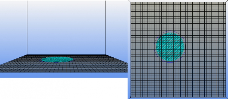
Here is an image of the g-code preview vs the print.
|
Re: Dual Extrusion Offset November 24, 2013 03:16PM |
Registered: 13 years ago Posts: 2,947 |
The problem with the entire print not being in the center could be the homing offest (M206) or it could be you have the bed center set incorrectly in the slicer.
| FFF Settings Calculator | Gcode post processors | Geometric Object Deposition Tool Blog |
| Tantillus.org | Mini Printable Lathe | How NOT to install a Pololu driver |
|
Re: Dual Extrusion Offset November 24, 2013 03:27PM |
Registered: 10 years ago Posts: 65 |
I have the bed size set 400x400mm and the center at 200x200mm using Absolute positioning. Here is my Prefix G-code that may be of help.
;(beginning of start.txt)
G90; (Absolute Positioning)
G28; (Homing back to X, Y and Z zero endstops.)
G92 X0 Y0 Z0; (set origin to current position)
G91; (Set to Relative Positioning)
G28; (Homing back to X, Y and Z zero endstops.)
G90; (Set to Absolute Positioning )
G92 E0; (zero the extruded length)
M218 T1 X56.5 Y0.0;
;(end of start.txt)
I called and asked the company about why they recommended the redundant positioning, but the answer I got was along the lines of the owner of the company knows what he is doing so there must be a reason. I haven't had any issues previously so I don't think that is the problem.
|
Re: Dual Extrusion Offset November 24, 2013 04:03PM |
Registered: 11 years ago Posts: 296 |
re Aberrant
Ok that gave some sense, but I do not have the final clue despite of this. Some confusion adds because your offset problem changes down this issue dialog :-(
Marlin use M218 for extruder offset as you have experienced, G9-10 is used for retraction purpose.
If enabled you may check EEprom settings for homing offsets just to verify.
Wonder why you need 2 homing sequences rel and abs position in prefix code?
|
Re: Dual Extrusion Offset November 24, 2013 05:38PM |
Registered: 10 years ago Posts: 65 |
Quote
justcurious
re Aberrant
Ok that gave some sense, but I do not have the final clue despite of this. Some confusion adds because your offset problem changes down this issue dialog :-(
Marlin use M218 for extruder offset as you have experienced, G9-10 is used for retraction purpose.
If enabled you may check EEprom settings for homing offsets just to verify.
Wonder why you need 2 homing sequences rel and abs position in prefix code?
I wonder the same. The sales rep couldn't explain why, but said there must be a reason... not a very good answer IMO. I have tried removing the relative and 're home lines of code and see no difference.
|
Re: Dual Extrusion Offset November 24, 2013 11:35PM |
Registered: 10 years ago Posts: 65 |
I thought it might be my perception but, it seems quite a few things are not as expected. First is the infill. The g-code is set to 0.1 infill. This appears to be much higher.
Also Comparing the scale and placement both seem off. The scale seems a bit larger than the g-code shows, and the position of the print seems offset as well.
This appears to be much higher than .1 infill correct? Here is the beginning G code generated from Slic3r.
"; generated by Slic3r 0.9.10b on 2013-11-23 at 00:56:47
; layer_height = 0.2
; perimeters = 3
; top_solid_layers = 3
; bottom_solid_layers = 3
; fill_density = .1
; perimeter_speed = 40
; infill_speed = 60
; travel_speed = 60
; nozzle_diameter = 0.35
; filament_diameter = 1.75
; extrusion_multiplier = .85
; perimeters extrusion width = 0.50mm
; infill extrusion width = 0.50mm
; solid infill extrusion width = 0.50mm
; top infill extrusion width = 0.50mm
; first layer extrusion width = 0.70mm"
Next I will try offsetting the entire print over 56.5mm (the x offset between print heads) and see if I can manually trick it to be centered.
Edited 2 time(s). Last edit at 11/24/2013 11:39PM by Aberrant.
|
Re: Dual Extrusion Offset November 25, 2013 01:54AM |
Registered: 10 years ago Posts: 40 |
Centering the print on the bed ... that brought back some memories to me, and I have just looked up my notes.
I too had problems with getting the print centered on the bed, and in the end, in spite of what I said earlier, I did not set my primary nozzle to 'all zeros' in the G10 command, but set the G10 command so that the object was printed centrally on the bed, I then set the offsets on the other nozzles to match. I remember finding it very difficult to get my head around how all this worked, and in the end I used a spread sheet to record the parameter changes and their effect. I used a very simple thin object to do the print tests, so that the job ran quickly.
Don't forget that in Slic3r the bed size is only used to effect the representation of the objects on the image of the platter, it does not effect the actual position of the object on the printer bed.
Harvey
|
Re: Dual Extrusion Offset November 25, 2013 03:13AM |
Registered: 10 years ago Posts: 65 |
Quote
HarveyC
Centering the print on the bed ... that brought back some memories to me, and I have just looked up my notes.
I too had problems with getting the print centered on the bed, and in the end, in spite of what I said earlier, I did not set my primary nozzle to 'all zeros' in the G10 command, but set the G10 command so that the object was printed centrally on the bed, I then set the offsets on the other nozzles to match. I remember finding it very difficult to get my head around how all this worked, and in the end I used a spread sheet to record the parameter changes and their effect. I used a very simple thin object to do the print tests, so that the job ran quickly.
Don't forget that in Slic3r the bed size is only used to effect the representation of the objects on the image of the platter, it does not effect the actual position of the object on the printer bed.
Harvey
Can you please clarify what you meant by the size is only used to effect the representation of the the objects and not the position on the print bed? How would it be possible to get an accurate representation of what will be printed.
|
Re: Dual Extrusion Offset November 25, 2013 03:23AM |
Registered: 13 years ago Posts: 2,947 |
Is it possible instead of:
M218 T1 X56.5 Y0.0; which has centre on T0 with the offset on T1
You need:
M218 T0 X-56.5 Y0.0; which would put the centre to T1 with the offset on T0
or
M218 T0 X-28.25 Y0.0; with this the centre would be in between the nozzles
M218 T1 X28.25 Y0.0; with this the centre would be in between the nozzles
| FFF Settings Calculator | Gcode post processors | Geometric Object Deposition Tool Blog |
| Tantillus.org | Mini Printable Lathe | How NOT to install a Pololu driver |
|
Re: Dual Extrusion Offset November 25, 2013 03:28AM |
Registered: 10 years ago Posts: 65 |
Quote
Sublime
Is it possible instead of:
M218 T1 X56.5 Y0.0; which has centre on T0 with the offset on T1
You need:
M218 T0 X-56.5 Y0.0; which would put the centre to T1 with the offset on T0
or
M218 T0 X-28.25 Y0.0; with this the centre would be in between the nozzles
M218 T1 X28.25 Y0.0; with this the centre would be in between the nozzles
Thanks for the tip. I know what you mean, but it think I need T0 to be centered on the print bed because the widest part of the print is printed using T0.
Another thought I had was to offset the whole print 56.5mm
|
Re: Dual Extrusion Offset November 25, 2013 01:01PM |
Registered: 10 years ago Posts: 40 |
In regard to your query about my comment on the bed size parameters in Slic3R, I am quoting from manual, which under 'Printer Settings, Size and Coordinates', states that the 'Bed Size' setting is taken from the wizard and is only used for previewing the model in the plater'.
Also (and I hope this is not adding to the confusion!!) I should have said earlier, that with the ReprapPro Mendel at least, before setting the individual extruder offsets with G10, you should set the base offset for the primary nozzle using M206 x y such that the primary extruder is placed over the cornet of the bed when you issue G1 X1 Y1 F.. Again this is all described the url that I previously quoted.
Don't know if any of this helps.
Harvey
|
Re: Dual Extrusion Offset November 25, 2013 01:26PM |
Registered: 11 years ago Posts: 296 |
You are probably assuming the leftmost extruder is E0?
Try to switch your assumption and exchange M218 commands so that rightmost extruder is E0 (T0) and offset is set to left most extruder E1 (T1).
I do not think it is fair you are consulting all community forums about this the same issue at same time and demand attention from a lot of people without learning anything particular and without giving feedback of your own testing .
.
Try to switch your assumption and exchange M218 commands so that rightmost extruder is E0 (T0) and offset is set to left most extruder E1 (T1).
I do not think it is fair you are consulting all community forums about this the same issue at same time and demand attention from a lot of people without learning anything particular and without giving feedback of your own testing
 .
.
|
Re: Dual Extrusion Offset November 26, 2013 01:49AM |
Registered: 10 years ago Posts: 65 |
Quote
HarveyC
You need to set the offsets with a G10 command not M218. The format of the G10 command is:-
G10 Pn Xn Yn Zn
Where:-
P is the number of the extruder (1st extruder is P0)
X is the x offset for this extruder
Y is the Y offset fopr this extruder
Z is the z offset, but (at least on my Reprap Pro Medel Tricolour) this is normally set to 0 as the z offset is set by the z limit switch.
Set your first extruder to all zeros (i.e G10 P0 X0 Y0 Z0)
then set the second one so that it prints in the correct place in relation to the first.
Don't forget to save the setting in firmware with M500 aftwerwards.
There is a very good description of this process at [www.reprappro.com]
Hope this helps
Harvey
Thank you Harvey, this does help, however I am using firmware that does not respond to the G10 command, instead I have to use M218 command. Below is the firmware type my Control Box sends upon connecting in Repetier Host:
FIRMWARE_NAME:Marlin V1; Sprinter/grbl mashup for gen6 FIRMWARE_URL:[www.mendel-parts.com] PROTOCOL_VERSION:1.0 MACHINE_TYPE:Mendel EXTRUDER_COUNT:2
I will use the same theory with the M218, since it works almost identically but only has an X and Y offset. I appreciate the help and link, I bookmarked it because I saw a ton of great info.
|
Re: Dual Extrusion Offset November 26, 2013 01:56AM |
Registered: 10 years ago Posts: 65 |
Quote
justcurious
You are probably assuming the leftmost extruder is E0?
Try to switch your assumption and exchange M218 commands so that rightmost extruder is E0 (T0) and offset is set to left most extruder E1 (T1).
I do not think it is fair you are consulting all community forums about this the same issue at same time and demand attention from a lot of people without learning anything particular and without giving feedback of your own testing.
I am not sure what you mean by switching extruder values, do you mean making X a negative value for T0 like Harvey mentioned?
About the feedback on testing, I have posted the results of each attempt. I have been working overtime recently, I have no time to do any printing. I will post the results of using X-56.5 to see if this corrects the offset issue.
|
Re: Dual Extrusion Offset November 26, 2013 02:13AM |
Registered: 11 years ago Posts: 296 |
|
Sharing Results November 30, 2013 02:41PM |
Registered: 10 years ago Posts: 65 |
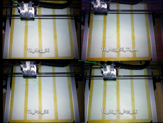
I am about to post a series of images and g-code that I used to generate these prints. I did four tests, and only changing the M218 command in the G-code.
I first tested using M218 T0 X-56.5 Y0.0;
Then M218 T1 X56.5 Y0.0;
The next two comparisons were using Two M218 commands, in order to define each print head
M218 T0 X0.0 Y0.0;
M218 T1 X56.5 Y0.0;
Then I tested
M218 T0 X-56.5 Y0.0;
M218 T1 X0.0 Y0.0;
I also want to mention I am loading the same .amf file in Slic3r and only changing the custom G-code within the Printer Settings profile.
The outcomes are NOT like I predicted. In fact, they left me more confused. Take a look at the following posts to see what I mean. I am going to post each test seperately, so things are more organized.
|
T0_Neg_56.5 November 30, 2013 03:10PM |
Registered: 10 years ago Posts: 65 |
; generated by Slic3r 0.9.10b on 2013-11-28 at 19:20:29
; layer_height = 0.2
; perimeters = 3
; top_solid_layers = 3
; bottom_solid_layers = 3
; fill_density = .1
; perimeter_speed = 40
; infill_speed = 60
; travel_speed = 60
; nozzle_diameter = 0.35
; filament_diameter = 1.75
; extrusion_multiplier = .85
; perimeters extrusion width = 0.50mm
; infill extrusion width = 0.50mm
; solid infill extrusion width = 0.50mm
; top infill extrusion width = 0.50mm
; first layer extrusion width = 0.70mm
G21 ; set units to millimeters
M107
M190 S70 ; wait for bed temperature to be reached
M104 S190 T0 ; set temperature
M104 S250 T1 ; set temperature
;(beginning of start.txt)
G90; (Absolute Positioning)
G28; (Homing back to X, Y and Z zero endstops.)
G92 X0 Y0 Z0; (set origin to current position)
G91; (Set to Relative Positioning)
G28; (Homing back to X, Y and Z zero endstops.)
G90; (Set to Absolute Positioning )
G92 E0; (zero the extruded length)
M218 T0 X-56.5 Y0.0;
;(end of start.txt)
|
T1_Pos_56.5 November 30, 2013 03:13PM |
Registered: 10 years ago Posts: 65 |
; generated by Slic3r 0.9.10b on 2013-11-22 at 00:59:15
; layer_height = 0.2
; perimeters = 3
; top_solid_layers = 3
; bottom_solid_layers = 3
; fill_density = .1
; perimeter_speed = 40
; infill_speed = 60
; travel_speed = 60
; nozzle_diameter = 0.35
; filament_diameter = 1.75
; extrusion_multiplier = .85
; perimeters extrusion width = 0.50mm
; infill extrusion width = 0.50mm
; solid infill extrusion width = 0.50mm
; top infill extrusion width = 0.50mm
; first layer extrusion width = 0.70mm
G21 ; set units to millimeters
M107
M190 S70 ; wait for bed temperature to be reached
M104 S190 T0 ; set temperature
M104 S250 T1 ; set temperature
;(beginning of start.txt)
G90; (Absolute Positioning)
G28; (Homing back to X, Y and Z zero endstops.)
G92 X0 Y0 Z0; (set origin to current position)
G91; (Set to Relative Positioning)
G28; (Homing back to X, Y and Z zero endstops.)
G90; (Set to Absolute Positioning )
G92 E0; (zero the extruded length)
M218 T1 X56.5 Y0.0;
;(end of start.txt)
|
T0_Neg_56.5_T1_0.0 November 30, 2013 03:16PM |
Registered: 10 years ago Posts: 65 |
; generated by Slic3r 0.9.10b on 2013-11-29 at 21:18:21
; layer_height = 0.2
; perimeters = 3
; top_solid_layers = 3
; bottom_solid_layers = 3
; fill_density = .02
; perimeter_speed = 40
; infill_speed = 60
; travel_speed = 60
; nozzle_diameter = 0.35
; filament_diameter = 1.75
; extrusion_multiplier = .85
; perimeters extrusion width = 0.50mm
; infill extrusion width = 0.50mm
; solid infill extrusion width = 0.50mm
; top infill extrusion width = 0.50mm
; first layer extrusion width = 0.70mm
G21 ; set units to millimeters
M107
M190 S70 ; wait for bed temperature to be reached
M104 S190 T0 ; set temperature
M104 S250 T1 ; set temperature
;(beginning of start.txt)
G90; (Absolute Positioning)
G28; (Homing back to X, Y and Z zero endstops.)
G92 X0 Y0 Z0; (set origin to current position)
G91; (Set to Relative Positioning)
G28; (Homing back to X, Y and Z zero endstops.)
G90; (Set to Absolute Positioning )
G92 E0; (zero the extruded length)
M218 T0 X-56.5 Y0.0;
M218 T1 X0.0 Y0.0;
;(end of start.txt)
|
T1_Pos_56.5_T0_0.0 November 30, 2013 03:18PM |
Registered: 10 years ago Posts: 65 |
; generated by Slic3r 0.9.10b on 2013-11-29 at 19:35:08
; layer_height = 0.2
; perimeters = 3
; top_solid_layers = 3
; bottom_solid_layers = 3
; fill_density = .02
; perimeter_speed = 40
; infill_speed = 60
; travel_speed = 60
; nozzle_diameter = 0.35
; filament_diameter = 1.75
; extrusion_multiplier = .85
; perimeters extrusion width = 0.50mm
; infill extrusion width = 0.50mm
; solid infill extrusion width = 0.50mm
; top infill extrusion width = 0.50mm
; first layer extrusion width = 0.70mm
G21 ; set units to millimeters
M107
M190 S70 ; wait for bed temperature to be reached
M104 S190 T0 ; set temperature
M104 S250 T1 ; set temperature
;(beginning of start.txt)
G90; (Absolute Positioning)
G28; (Homing back to X, Y and Z zero endstops.)
G92 X0 Y0 Z0; (set origin to current position)
G91; (Set to Relative Positioning)
G28; (Homing back to X, Y and Z zero endstops.)
G90; (Set to Absolute Positioning )
G92 E0; (zero the extruded length)
M218 T0 X0.0 Y0.0;
M218 T1 X56.5 Y0.0;
;(end of start.txt)
|
Re: Sharing Results November 30, 2013 03:20PM |
Registered: 10 years ago Posts: 65 |
After comparing the photos I took, I see there is no change in any of the prints except for the one with the T1 Pos 56. This is also the print that scaled in size. I used the same .amf file for all of the prints. I see that the scale has increased, but the positioning is still shifted left relative to its scale. I am now thinking about testing out the command G92 X0 Y0 Z0; (set origin to current position)
I may need to change the X value to compensate for the first print head? Any help would be greatly appreciated.
Edited 1 time(s). Last edit at 11/30/2013 03:43PM by Aberrant.
I may need to change the X value to compensate for the first print head? Any help would be greatly appreciated.
Edited 1 time(s). Last edit at 11/30/2013 03:43PM by Aberrant.
|
Results_Comparison November 30, 2013 03:53PM |
Registered: 10 years ago Posts: 65 |
Sorry, only registered users may post in this forum.
