First parts analysis....
Posted by Davek0974
|
First parts analysis.... March 02, 2014 12:46PM |
Registered: 10 years ago Posts: 776 |
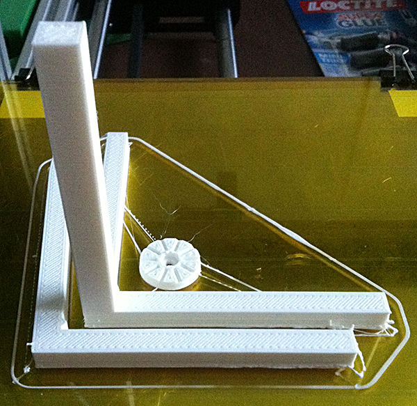
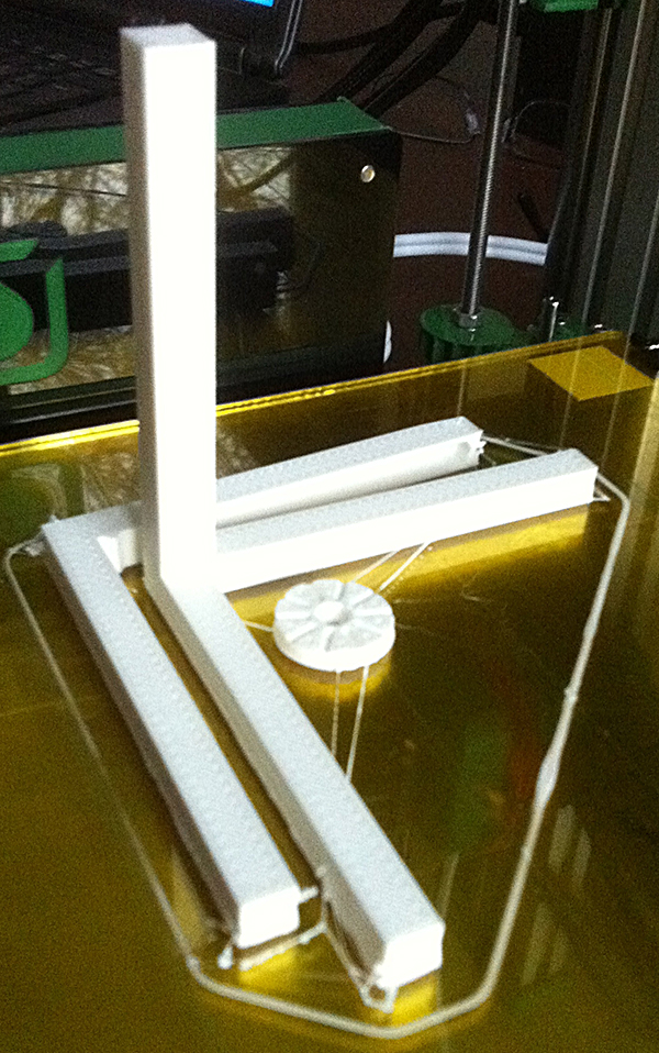
Attached are pictures of my first prints - the Ormaxis.g set and a new belt tensioner set from the forum.
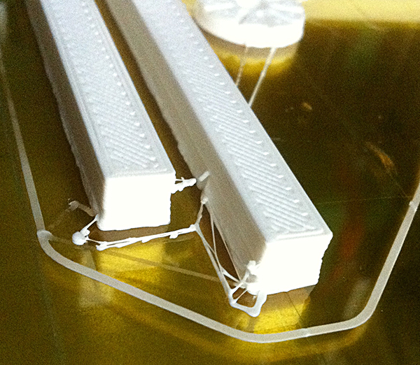
I think the lower edges of the ormaxis parts show indications of a slightly slack y axis belt, can anyone confirm??
The vertical column was 100% perfect, i couldn't hope for a better print on that part.
overall a successful day
thanks for all the tips so far.
BYW does anyone know hot to find the RS model number, i see members with it as part of their sig
|
Re: First parts analysis.... March 02, 2014 01:48PM |
Registered: 10 years ago Posts: 578 |
|
Re: First parts analysis.... March 02, 2014 02:29PM |
Registered: 10 years ago Posts: 776 |
|
Re: First parts analysis.... March 02, 2014 02:34PM |
Registered: 10 years ago Posts: 578 |
|
Re: First parts analysis.... March 02, 2014 03:14PM |
Registered: 10 years ago Posts: 776 |
That explains the err, nice colour ones then 
What's the opinion on my first prints?
I did notice that the distance between the measuring pip and the screw on the orthogonal part is 75mm and not the 78mm as listed in the manual, is this an issue?
As I had bed compensation running, does the test piece need re-doing when the bed levelling is altered, could be a time consuming issue if so
|
Re: First parts analysis.... March 02, 2014 03:24PM |
Registered: 10 years ago Posts: 14,672 |
Those look excellent for first prints, especially considering that the gcode files supplied were probably configured for the old firmware, so the extruder temperature will be a little higher than optimum. I agree that your y-belt may be a little slack.
Large delta printer [miscsolutions.wordpress.com], E3D tool changer, Robotdigg SCARA printer, Crane Quad and Ormerod
Disclosure: I design Duet electronics and work on RepRapFirmware, [duet3d.com].
Large delta printer [miscsolutions.wordpress.com], E3D tool changer, Robotdigg SCARA printer, Crane Quad and Ormerod
Disclosure: I design Duet electronics and work on RepRapFirmware, [duet3d.com].
|
Re: First parts analysis.... March 02, 2014 03:36PM |
Registered: 11 years ago Posts: 103 |
>... on the orthogonal part is 75mm not the 78mm
I asked this as well a few days (weeks?) ago. got at least some reassurence from markbee.
[forums.reprap.org] and following
I asked this as well a few days (weeks?) ago. got at least some reassurence from markbee.
[forums.reprap.org] and following
|
Re: First parts analysis.... March 02, 2014 03:38PM |
Registered: 10 years ago Posts: 776 |
Great, I printed off the y-belt tensioners and will fit them as part of the first overhaul/upgrade soon, the temperatures were lower on that job as they were sliced with my new settings and apart from the first thread of the base layer which did not seem to join the body too well, look excellent.
Another RS Ormerod Mk1 meets the world
Retired now but I used to make....
CNC Machined Mk1 aluminium bed support plates for the Ormerod
CNC machined X-plates and ribs for Mk1 & Mk2 Ormerods
CNC machined bed support arms for the Mk2 Ormerod.
Dual Hot-End heatsink blocks.
Another RS Ormerod Mk1 meets the world
Retired now but I used to make....
CNC Machined Mk1 aluminium bed support plates for the Ormerod
CNC machined X-plates and ribs for Mk1 & Mk2 Ormerods
CNC machined bed support arms for the Mk2 Ormerod.
Dual Hot-End heatsink blocks.
|
Re: First parts analysis.... March 02, 2014 04:24PM |
Registered: 10 years ago Posts: 578 |
|
Re: First parts analysis.... March 02, 2014 04:34PM |
Registered: 10 years ago Posts: 776 |
Lol
Next job is feeding in the orthogonal compensation figures.
Then I'm thinking of either printing some spares for the beast or altering the bed mountings and rails as I have a 0.9mm dip in one corner, it's been compensated out but I think it can be made better.
As for prototypes, err, dunno, haven't even learnt 3d cad yet I'm only just picking up 2d cad for a CNC plasma cutter I recently built for my main hobby of metalworking.
Then I need a decent spool holder stand
Another RS Ormerod Mk1 meets the world
Retired now but I used to make....
CNC Machined Mk1 aluminium bed support plates for the Ormerod
CNC machined X-plates and ribs for Mk1 & Mk2 Ormerods
CNC machined bed support arms for the Mk2 Ormerod.
Dual Hot-End heatsink blocks.
Next job is feeding in the orthogonal compensation figures.
Then I'm thinking of either printing some spares for the beast or altering the bed mountings and rails as I have a 0.9mm dip in one corner, it's been compensated out but I think it can be made better.
As for prototypes, err, dunno, haven't even learnt 3d cad yet
I'm only just picking up 2d cad for a CNC plasma cutter I recently built for my main hobby of metalworking.Then I need a decent spool holder stand
Another RS Ormerod Mk1 meets the world
Retired now but I used to make....
CNC Machined Mk1 aluminium bed support plates for the Ormerod
CNC machined X-plates and ribs for Mk1 & Mk2 Ormerods
CNC machined bed support arms for the Mk2 Ormerod.
Dual Hot-End heatsink blocks.
|
Re: First parts analysis.... March 02, 2014 04:40PM |
Registered: 10 years ago Posts: 1,230 |
|
Re: First parts analysis.... March 02, 2014 04:47PM |
Registered: 10 years ago Posts: 578 |
LOL funny you chipped in just then Erik, I was busy looking up your all-metal spool holder to give Davek something to aim at And here it is : [forums.reprap.org]
Cheers
Ray
And here it is : [forums.reprap.org]Cheers
Ray
|
Re: First parts analysis.... March 02, 2014 04:51PM |
Registered: 10 years ago Posts: 578 |
Quote
Davek0974
As for prototypes, err, dunno, haven't even learnt 3d cad yet sad smiley
If you're at all into scripting or programming, openScad is pretty powerful and although it doesn't let you do much mouse stuff, what you ask for is what you get - well worth a try www.openscad.org
Ray
|
Re: First parts analysis.... March 02, 2014 04:52PM |
Registered: 10 years ago Posts: 776 |
Quote
rayhicks
LOL funny you chipped in just then Erik, I was busy looking up your all-metal spool holder to give Davek something to aim at
Cheers
Ray
ROFL!
Need to strengthen my desk to take that beast
Sure I saw a link to some stl files for a roll stand somewhere
Another RS Ormerod Mk1 meets the world
Retired now but I used to make....
CNC Machined Mk1 aluminium bed support plates for the Ormerod
CNC machined X-plates and ribs for Mk1 & Mk2 Ormerods
CNC machined bed support arms for the Mk2 Ormerod.
Dual Hot-End heatsink blocks.
|
Re: First parts analysis.... March 03, 2014 05:00AM |
Registered: 10 years ago Posts: 145 |
I made the Bearing with herringbone gears as a test piece some time ago.
I have since thought of using it as a bearing for a spool mount (horizontal) - so I printed a base to fit through the sun gear (a bit too small diameter), and a spool holder to fit over the bearing
The spool holder will take my big spools from Galactic Warehouse, as well as the one supplied with the kit (it fits in the four slots).
Seems to work pretty well, but I need to print a bigger base with a few screw holes to hold it down firmly.
Greg
Ormerod #17
I have since thought of using it as a bearing for a spool mount (horizontal) - so I printed a base to fit through the sun gear (a bit too small diameter), and a spool holder to fit over the bearing

The spool holder will take my big spools from Galactic Warehouse, as well as the one supplied with the kit (it fits in the four slots).
Seems to work pretty well, but I need to print a bigger base with a few screw holes to hold it down firmly.
Greg
Ormerod #17
|
Re: First parts analysis.... March 03, 2014 05:05AM |
Registered: 10 years ago Posts: 859 |
hihihi my spool holder....
Please send me a PM if you have suggestions, or problems with Big Blue 360.
I won't see comments in threads, as I move around to much.
Working Link to Big Blue 360 Complete


Please send me a PM if you have suggestions, or problems with Big Blue 360.
I won't see comments in threads, as I move around to much.
Working Link to Big Blue 360 Complete
|
Re: First parts analysis.... March 03, 2014 06:20AM |
Registered: 10 years ago Posts: 14,672 |
Quote
GregL
I made the Bearing with herringbone gears as a test piece some time ago.
I have since thought of using it as a bearing for a spool mount (horizontal) - so I printed a base to fit through the sun gear (a bit too small diameter), and a spool holder to fit over the bearing
Great idea! I was wondering what to do with the bearing I printed. Can you publish your STLs (also .scad files if you used openscad)?
Large delta printer [miscsolutions.wordpress.com], E3D tool changer, Robotdigg SCARA printer, Crane Quad and Ormerod
Disclosure: I design Duet electronics and work on RepRapFirmware, [duet3d.com].
|
Re: First parts analysis.... March 03, 2014 06:40AM |
Registered: 10 years ago Posts: 145 |
The base support needs to be bigger (with some mounting holes) - it allows 1mm clearance below the sun gear.
The bearing does not fit completely into the spool holder - another 1mm clearance, so the base and the spool holder will not rub against each other.
The stl file is the one I printed, but it did not deal very well with the big overhang, and the change of diameter where the rim of the bearing fits - needed quite a bit of cutting of stray strands.
The scad file is slightly updated to reduce the big overhang, and chamfer that change of diameter.
Removing a couple of the // before the two translate([60,0,0]) will separate out the two parts
Greg
edited to tidy up the scad file - it had some junk in there
Edited 2 time(s). Last edit at 03/03/2014 07:12AM by GregL.
Ormerod #17
|
Re: First parts analysis.... March 03, 2014 10:07AM |
Registered: 10 years ago Posts: 2,472 |
Quote
rayhicks
Quote
Davek0974
As for prototypes, err, dunno, haven't even learnt 3d cad yet sad smiley
If you're at all into scripting or programming, openScad is pretty powerful and although it doesn't let you do much mouse stuff, what you ask for is what you get - well worth a try www.openscad.org
Ray
I was using the very expensive 3D CAD software we have at work, but then wanted to do a small mod to a design I downloaded in OpenScad. I was initially upset that the expensive CAD application could not import that type of file, so I had to learn a bit. Now I am completely hooked on OpenScad and use it in preference to the expensive tool. Working out the code for the design of the main shape takes a bit more time than the GUI CAD tool, but making changes and tweaks is far quicker and easier, and I'm slowly building up my own module library that makes it faster to do things I do frequently such as applying a draft (small angle) to the sides of a box, or filleting corners etc. With OpenScad I can also complete a design before I have all the measurements I need, and then simply change the declared variables once I have been able to take those measurements. Changing the size of something in the expensive program can be a major task if the change has a knock-on effect to the positions and sizes of other structures. It is especially good when needing to adjust the angle of bits of a design, which is a nightmare with the GUI CAD system, but with OpenScad you just make everything that may need to be rotated as a module, and rotate that as you want by editing a single variable.
I well recommend anyone starting in 3D design to bite the bullet and suffer the learning curve - and not only that, it's completely free software!
Dave
(#106)
|
Re: First parts analysis.... March 03, 2014 10:07AM |
Registered: 10 years ago Posts: 145 |
Thought I would see if I could make something fly
The wings (~340mm span) are single wall, with some structure inside - but no infill
wings 22g
body 13g
(at 2p per gram that is about 70p
PlayDoh ballast 10g (don't tell the grandchildren)
It flew slightly better than a 'lead ballon' - but not by much.
Need a bigger wing area to cope with the weight - maybe a Vulcan like delta.
Greg
Ormerod #17
|
Re: First parts analysis.... March 04, 2014 04:18PM |
Registered: 10 years ago Posts: 776 |
I reprinted the orthogonal test piece tonight following my bed rebuild, this time I sliced the stl in slic3r using the custom profile for ormerod with the added lines for temperature controls and waiting for warm up.
The result on the X and Y surfaces was much improved following the fitting of the two part Y belt tensioners, very clean and straight.
However, when it had finished I noticed some ridges or banding on the Z part, to the eye they appear to be about 1mm apart , very shallow but noticeable and were not on the first part which was pre-sliced. They only start at the point the vertical column starts to rise, the vase legs are perfect.
It's not critical but as it was not on the first run, I know it can do better
Can't really get macro photos with my phone so tricky to get a picture up.
Any pointers to check for?
Another RS Ormerod Mk1 meets the world
Retired now but I used to make....
CNC Machined Mk1 aluminium bed support plates for the Ormerod
CNC machined X-plates and ribs for Mk1 & Mk2 Ormerods
CNC machined bed support arms for the Mk2 Ormerod.
Dual Hot-End heatsink blocks.
|
Re: First parts analysis.... March 05, 2014 01:01PM |
Registered: 10 years ago Posts: 2,472 |
Quote
Davek0974
I reprinted the orthogonal test piece tonight following my bed rebuild, this time I sliced the stl in slic3r using the custom profile for ormerod with the added lines for temperature controls and waiting for warm up.
The result on the X and Y surfaces was much improved following the fitting of the two part Y belt tensioners, very clean and straight.
However, when it had finished I noticed some ridges or banding on the Z part, to the eye they appear to be about 1mm apart , very shallow but noticeable and were not on the first part which was pre-sliced. They only start at the point the vertical column starts to rise, the vase legs are perfect.
It's not critical but as it was not on the first run, I know it can do better
Can't really get macro photos with my phone so tricky to get a picture up.
Any pointers to check for?
What did you set your layer height to when you sliced it? If the layer height is not set to be an exact number of steps you will get a slightly uneven effect because some layers will have one step more or less than other layers due to the firmware rounding each Z height to the nearest step.
Dave
(#106)
|
Re: First parts analysis.... March 05, 2014 03:41PM |
Registered: 10 years ago Posts: 776 |
Quote
dmould
Quote
Davek0974
I reprinted the orthogonal test piece tonight following my bed rebuild, this time I sliced the stl in slic3r using the custom profile for ormerod with the added lines for temperature controls and waiting for warm up.
The result on the X and Y surfaces was much improved following the fitting of the two part Y belt tensioners, very clean and straight.
However, when it had finished I noticed some ridges or banding on the Z part, to the eye they appear to be about 1mm apart , very shallow but noticeable and were not on the first part which was pre-sliced. They only start at the point the vertical column starts to rise, the vase legs are perfect.
It's not critical but as it was not on the first run, I know it can do better
Can't really get macro photos with my phone so tricky to get a picture up.
Any pointers to check for?
What did you set your layer height to when you sliced it? If the layer height is not set to be an exact number of steps you will get a slightly uneven effect because some layers will have one step more or less than other layers due to the firmware rounding each Z height to the nearest step.
Dave
(#106)
It was default for the ormerod files, just checked and it's 0.4mm with first layer at 0.35mm
Is there a better setting?
Another RS Ormerod Mk1 meets the world
Retired now but I used to make....
CNC Machined Mk1 aluminium bed support plates for the Ormerod
CNC machined X-plates and ribs for Mk1 & Mk2 Ormerods
CNC machined bed support arms for the Mk2 Ormerod.
Dual Hot-End heatsink blocks.
|
Re: First parts analysis.... March 06, 2014 06:07AM |
Registered: 10 years ago Posts: 776 |
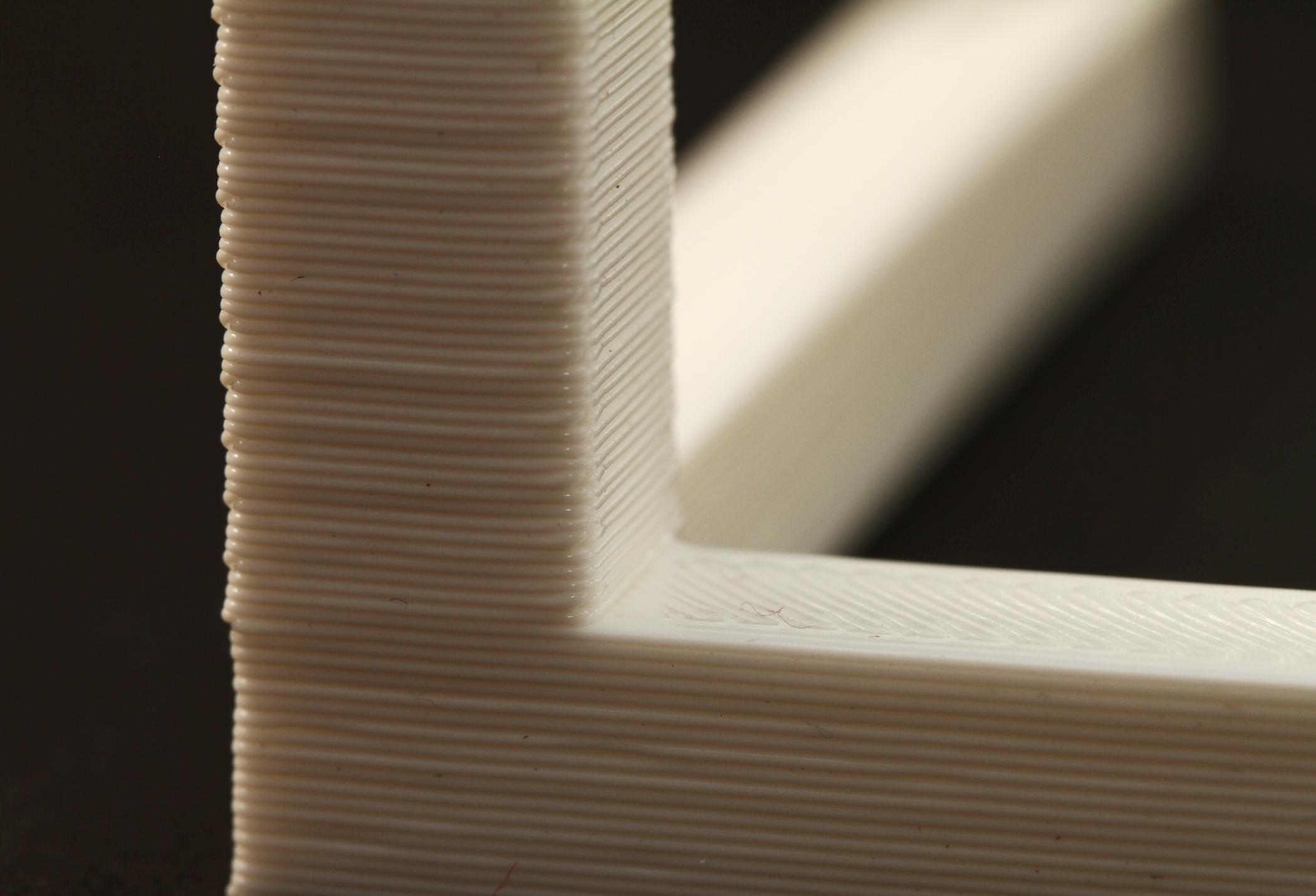
I think you can see the issue in the picture attached.
It looks like it changes every four layers but only on the vertical part, the base is smooth all the way up.
Any ideas?
Another RS Ormerod Mk1 meets the world
Retired now but I used to make....
CNC Machined Mk1 aluminium bed support plates for the Ormerod
CNC machined X-plates and ribs for Mk1 & Mk2 Ormerods
CNC machined bed support arms for the Mk2 Ormerod.
Dual Hot-End heatsink blocks.
|
Re: First parts analysis.... March 06, 2014 07:13AM |
Registered: 10 years ago Posts: 2,472 |
Quote
Davek0974
Quote
dmould
What did you set your layer height to when you sliced it? If the layer height is not set to be an exact number of steps you will get a slightly uneven effect because some layers will have one step more or less than other layers due to the firmware rounding each Z height to the nearest step.
It was default for the ormerod files, just checked and it's 0.4mm with first layer at 0.35mm
Is there a better setting?
I think you meant to type 0.24mm rather than 0.4mm If so then yes, that setting works fine for me. Maybe check whether the finished height is correct - if not it could mean that your Z motor is skipping steps occasionally.
Dave
(#106)
|
Re: First parts analysis.... March 06, 2014 07:40AM |
Registered: 10 years ago Posts: 776 |
no, slic3r was definitely set for 0.4 / 0.35mm
If the axis was slipping, it wouldn't be so precise surely, every 4 layers???
Another RS Ormerod Mk1 meets the world
Retired now but I used to make....
CNC Machined Mk1 aluminium bed support plates for the Ormerod
CNC machined X-plates and ribs for Mk1 & Mk2 Ormerods
CNC machined bed support arms for the Mk2 Ormerod.
Dual Hot-End heatsink blocks.
|
Re: First parts analysis.... March 06, 2014 07:52AM |
Registered: 10 years ago Posts: 48 |
|
Re: First parts analysis.... March 06, 2014 07:57AM |
Registered: 10 years ago Posts: 776 |
Hmm, possible, will check.
I have just noticed that i have two different sets of slic3r settings, both were downloads and one shows the layer as 0.4 / 0.35mm which is what i used at home, the other shows the layer as 0.24 / 0.24mm which I have just found at work on my test bed for slic3r.
Can someone point me to exactly which one is the correct / best set of profiles to be using???
One uses honeycomb infill the other uses rectilinear as well.
Slight confusion here
Another RS Ormerod Mk1 meets the world
Retired now but I used to make....
CNC Machined Mk1 aluminium bed support plates for the Ormerod
CNC machined X-plates and ribs for Mk1 & Mk2 Ormerods
CNC machined bed support arms for the Mk2 Ormerod.
Dual Hot-End heatsink blocks.
|
Re: First parts analysis.... March 06, 2014 07:57AM |
Registered: 10 years ago Posts: 2,472 |
Quote
Davek0974
no, slic3r was definitely set for 0.4 / 0.35mm
If the axis was slipping, it wouldn't be so precise surely, every 4 layers???
Set it to 0.24, which should have been the default. It is quite possible that the Z motor misses a step at regular intervals if there is something binding in one place on the leadscrew train.
Dave
(#106)
|
Re: First parts analysis.... March 06, 2014 02:30PM |
Registered: 10 years ago Posts: 776 |
I have the correct profiles installed now, the screen shows "ormerod 0.5" in pronterface ini boxes now.
Got some gears printing, see how it goes.
Another RS Ormerod Mk1 meets the world
Retired now but I used to make....
CNC Machined Mk1 aluminium bed support plates for the Ormerod
CNC machined X-plates and ribs for Mk1 & Mk2 Ormerods
CNC machined bed support arms for the Mk2 Ormerod.
Dual Hot-End heatsink blocks.

Sorry, only registered users may post in this forum.