Best Z-axis configuration?
Posted by Edvardas
|
Re: Best Z-axis configuration? November 19, 2015 08:54AM |
Registered: 8 years ago Posts: 346 |
Quote
Edvardas
Quote
filipeCampos
Only speaking of the mechanism to move the bed and not the bed structure or linear motion. AndreasL is an interesting concept but i still think the use of lead screw is better.
One lead screw of 40cm has cost me 18€ on ebay and more 2€ for the coupler. If you go to the AndreasL solution it will be really cheaper? You still need to buy the belt, pulley and bearings. The total can be less of 20€.. but it really worth it? You still need to solve to problem of the missing reduction, something you automatically have in an lead screw solution. The belt allow fast speed, but you need this type of speed in the z axis?
I think there is better way to save money...
If a belt would be used on a cantilevered bed then it is a very simple design with few parts like on an original smartrapcore.
I think that belt on a Z-axis would be more forgiving to any design flaws. Screws need to be mounted just right or they cause trouble. Now if I want to use two screws I would need leadscrews with machined ends in order to fit them between bearings at both ends. I would still need pulleys and just right lenght close ended belt to run these screws of a single motor. Thats is quite a complicated mechanism. TR16x4 mechined-end leadscrew with a nut costs 30 euros for a set off dold-mechatronics.
Here is some information on the correct mounting techniques for leadscrews [blog.helixlinear.com] You can mount a single leadscrew according to A technique but to be able to use two screws driven off a single motor one would need use technique B. For this one would need a high quality perfectly straight lead screw otherwise screw would transmit any irreguliarities to the bed and to the print itself.
I agree with you, if you do not have a rigid frame lead screw can be difficult to setup correctly and can not be the best option. This belt system appears to be a lot more forgiving. I was using was example the setup i have, i only use one lead screw.
But the missing reduction of the belt system is a deal break to me, i think you need to somehow add a least an reduction of 1:4.
You will have several possible problems because you are using an low reduction. it will be necessary to put a good amount of ampere in the motor, this will produce more heat. When printing, the motor need to always have current. After the print you must send an command to lower down the bed before cutting the motor power, this is not the default configuration you have in the sliders. If you update or change of slider and forget to change the default ending gcode you can have an bad surprise at the end of the print. I normally use the gcode command to cut off the power of the motor to change filament or only to move the carriage, with this setup you must be careful before using the functionality.
Modify the setup to have a good reduction and then it will be a great system.
Edited 1 time(s). Last edit at 11/19/2015 08:57AM by filipeCampos.
|
Re: Best Z-axis configuration? November 19, 2015 09:12AM |
Registered: 9 years ago Posts: 346 |
Quote
filipeCampos
...
Modify the setup to have a good reduction and then it will be a great system.
Using a geared stepper will give you all those things. Will hold when powered off, very high reduction and low power use - Still very reasonable costs.
2:1 using belts is the limit I think. If you want 4:1 or more then you need to apply real gears... Thus geared stepper.
|
Re: Best Z-axis configuration? November 19, 2015 09:22AM |
Registered: 10 years ago Posts: 179 |
Quote
filipeCampos
I agree with you, if you do not have a rigid frame lead screw can be difficult to setup correctly and can not be the best option. This belt system appears to be a lot more forgiving. I was using was example the setup i have, i only use one lead screw.
But the missing reduction of the belt system is a deal break to me, i think you need to somehow add a least an reduction of 1:4.
You will have several possible problems because you are using an low reduction. it will be necessary to put a good amount of ampere in the motor, this will produce more heat. When printing, the motor need to always have current. After the print you must send an command to lower down the bed before cutting the motor power, this is not the default configuration you have in the sliders. If you update or change of slider and forget to change the default ending gcode you can have an bad surprise at the end of the print. I normally use the gcode command to cut off the power of the motor to change filament or only to move the carriage, with this setup you must be careful before using the functionality.
Modify the setup to have a good reduction and then it will be a great system.
It is not only about a rigid frame but also how square it is. My frame is made of 2020 profiles and contains 60 metal corner brackets and extra brace beams. It is rigid but I do not think it is perfectly square. Leadscrews must be paralel to the smooth rods. This might be easier with cantilevered bed but as a number of screws and smooth rods increases it can get tricky.
As for resolution you are right. I wonder how precise one can set first layer gap without getting into changing the drive ratios.
As for crashing the bed once current is cut off- I think there a solutions such as using springs on smooth rods.
|
Re: Best Z-axis configuration? November 19, 2015 09:24AM |
Registered: 10 years ago Posts: 179 |
Quote
LarsK
Quote
filipeCampos
...
Modify the setup to have a good reduction and then it will be a great system.
Using a geared stepper will give you all those things. Will hold when powered off, very high reduction and low power use - Still very reasonable costs.
2:1 using belts is the limit I think. If you want 4:1 or more then you need to apply real gears... Thus geared stepper.
Geared steppers are supposed to have backlash, no? Although sli3der 3d printer use geared stepper with a great results.
|
Re: Best Z-axis configuration? November 19, 2015 09:41AM |
Registered: 9 years ago Posts: 346 |
|
Re: Best Z-axis configuration? November 19, 2015 09:49AM |
Registered: 10 years ago Posts: 179 |
Quote
LarsK
Quote
Edvardas
Geared steppers are supposed to have backlash, no? Although sli3der 3d printer use geared stepper with a great results.
Only a problem if you move the bed up and down doing print. If you just go down ( one direction) the backlash should be irellevant.
I do use Z-lift as otherwise nozzle charshes into a print while traveling so that is relevant to me.
|
Re: Best Z-axis configuration? November 19, 2015 12:08PM |
Registered: 9 years ago Posts: 722 |
Hi guys,
Big overang needs a very stiff and probably heavyer Z carriage. Put it into your BOM.
you need a perfect alignment between 3 components : 2 guides, 1 screw. It's not realy easy for ordinary people.
Leadscrews needsaligment close to perfection or you have some jam and the nut will be damaged.
Cheap or damaged nut, and there will be backlash in the nut and you may have issues.
On my CNC, I need to change the nut each year, maybe next year I will need to change the screw too.
Realthor is right, with cheap leadscrews/nuts, you'd rather have two systems facing eachother : 4 guides and 2 screws.
Appreciate you will have 6 components to align finely. I experienced this is bid deal.
If you want to prevent any missalignment, you need a belt between the two screws.
I believe a screw system as good as AndreasL's should be more expensive in components and structure.
With the AndreasL system you have the bed attached on two points at the oposite sides.
As you said, belt is extremely permissive - and very durable. Any missaligment would not induce a lot big errors.
1 single belt, 2 guides, and a stable bed. No backlash, no possible missalignment. It's hard to beat.
You can build your system with standard measuring tools and ordinary skills.
(It was experienced by Fabrice974 with his brand new Fabcore, updated with two motors on Z to keep the hoist system).
I think a single motor with a reduction do as well for less money.
I don't want micro-stepping on the Z axis and I will explain why.
Fisrt, microstepping is good in transitions. It gives a smooth motion and reduce operating noise.
But we don't need that on the Z axis. It's just a quick shift movement, one time per layer.
Seccond, a stepper motor can stop only on a full step. Only full step and half step position are true.
Others are estimated with a growing percentage of errors. And the holding torque on microsteps is greatly diminished.
So you want a resolution that allows your Z stepper motor to stop on full steps and desactivate microstepping.
As you have selected a component (screw, rack or belt) with a pitch that is a multiplication of the dispacement you get at full step, it's just perfect !
The AndreasL system allows 0.2mm per full step. For most people it's pretty enough.
@LarsK, we use regular 17HS8401, no geared motors, but I rework AndreasL version to be able to print <0.2mm layers.
The smallest GT2 pulley you can easily buy is 16 tooth. So for 1:4, you should need a 64 teeth pulley (you can print one) and its diameter do not exceed the nema17 width
The bed level is set manualy so you've got the right distance anywhere on the bed.
I thought 20T pulley's pitch was 12.73mm, so there's no perfect match for 20T (between 604 and 624).
On the version I'm working on, I used 16T pulleys (smaller diameter = better torque) and use 2xF623ZZ bearings are idler pulleys.
We can get perfect idler pulleys but its more expensive than bearings. And bearings works just fine.
They're pretty close to the GT2 16T (0.1mm delta in radius) and it's mostly a constant pitch diameter. For the tooth side of the belt, I use regular GT2 pulleys between MF105ZZ bearings.
++JM
Technicaly, a lead screw is a pivot point, you can triangulate 1 screw and 2 guides, but you will have a big overhang.Quote
filipeCampos
Only speaking of the mechanism to move the bed and not the bed structure or linear motion. AndreasL is an interesting concept but i still think the use of lead screw is better.
One lead screw of 40cm has cost me 18€ on ebay and more 2€ for the coupler. If you go to the AndreasL solution it will be really cheaper? You still need to buy the belt, pulley and bearings. The total can be less of 20€.. but it really worth it? You still need to solve to problem of the missing reduction, something you automatically have in an lead screw solution. The belt allow fast speed, but you need this type of speed in the z axis?
I think there is better way to save money...
Big overang needs a very stiff and probably heavyer Z carriage. Put it into your BOM.
you need a perfect alignment between 3 components : 2 guides, 1 screw. It's not realy easy for ordinary people.
Leadscrews needsaligment close to perfection or you have some jam and the nut will be damaged.
Cheap or damaged nut, and there will be backlash in the nut and you may have issues.
On my CNC, I need to change the nut each year, maybe next year I will need to change the screw too.
Realthor is right, with cheap leadscrews/nuts, you'd rather have two systems facing eachother : 4 guides and 2 screws.
Appreciate you will have 6 components to align finely. I experienced this is bid deal.
If you want to prevent any missalignment, you need a belt between the two screws.
I believe a screw system as good as AndreasL's should be more expensive in components and structure.
With the AndreasL system you have the bed attached on two points at the oposite sides.
As you said, belt is extremely permissive - and very durable. Any missaligment would not induce a lot big errors.
1 single belt, 2 guides, and a stable bed. No backlash, no possible missalignment. It's hard to beat.
You can build your system with standard measuring tools and ordinary skills.
Sadly, the hoist system of the smartrap cannot be use, because the two carriages would be independant, that's not what we want.Quote
realthor
The original smartrap has a different size (larger) upper pulley that acts as a reduction as I read somewhere. Can't that solution be applied for AndreasL's solution as well?
@J-Max: you don't want to use micro-stepping? Even a modest 4x or 8x would get you to the desired resolution.
(It was experienced by Fabrice974 with his brand new Fabcore, updated with two motors on Z to keep the hoist system).
I think a single motor with a reduction do as well for less money.
I don't want micro-stepping on the Z axis and I will explain why.
Fisrt, microstepping is good in transitions. It gives a smooth motion and reduce operating noise.
But we don't need that on the Z axis. It's just a quick shift movement, one time per layer.
Seccond, a stepper motor can stop only on a full step. Only full step and half step position are true.
Others are estimated with a growing percentage of errors. And the holding torque on microsteps is greatly diminished.
So you want a resolution that allows your Z stepper motor to stop on full steps and desactivate microstepping.
As you have selected a component (screw, rack or belt) with a pitch that is a multiplication of the dispacement you get at full step, it's just perfect !
The AndreasL system allows 0.2mm per full step. For most people it's pretty enough.
@LarsK, we use regular 17HS8401, no geared motors, but I rework AndreasL version to be able to print <0.2mm layers.
With a 1:4 reduction you can reach 0,05mm per full step. Most 3d printers can't reach that Z resolution.Quote
Edvardas
I think that 4:1 reduction via pulleys would be complicated to achieve. Better do 2:1 belt reduction (40T and 20T pulleys) and use 400 steps per revolution stepper motor. That would be more compact and easier to source parts.
The smallest GT2 pulley you can easily buy is 16 tooth. So for 1:4, you should need a 64 teeth pulley (you can print one) and its diameter do not exceed the nema17 width
I awnsered about micro-stepping earlyer. The Z0 is set upon Zmin and is repeatable.Quote
Edvardas
What microstepping is used on Z-axis? What is the problem with current 0.2mm per step setup? Is Z0 easy to set and repeatable?
I could redesign AndreasL design on solidworks to be used for 2020 profiles and make it all beefier. I would also use 624 bearings for idlers as its size is almost the same as 20T GT2 pulley. Or do you know an European supplier of GT2 idler pulleys? Actually on AndreasL design only one idler pulley would be needed as the rest of idlers run on non-toothed side of belt.
The bed level is set manualy so you've got the right distance anywhere on the bed.
I thought 20T pulley's pitch was 12.73mm, so there's no perfect match for 20T (between 604 and 624).
On the version I'm working on, I used 16T pulleys (smaller diameter = better torque) and use 2xF623ZZ bearings are idler pulleys.
We can get perfect idler pulleys but its more expensive than bearings. And bearings works just fine.
They're pretty close to the GT2 16T (0.1mm delta in radius) and it's mostly a constant pitch diameter. For the tooth side of the belt, I use regular GT2 pulleys between MF105ZZ bearings.
++JM
|
Re: Best Z-axis configuration? November 19, 2015 01:54PM |
Registered: 9 years ago Posts: 1,035 |
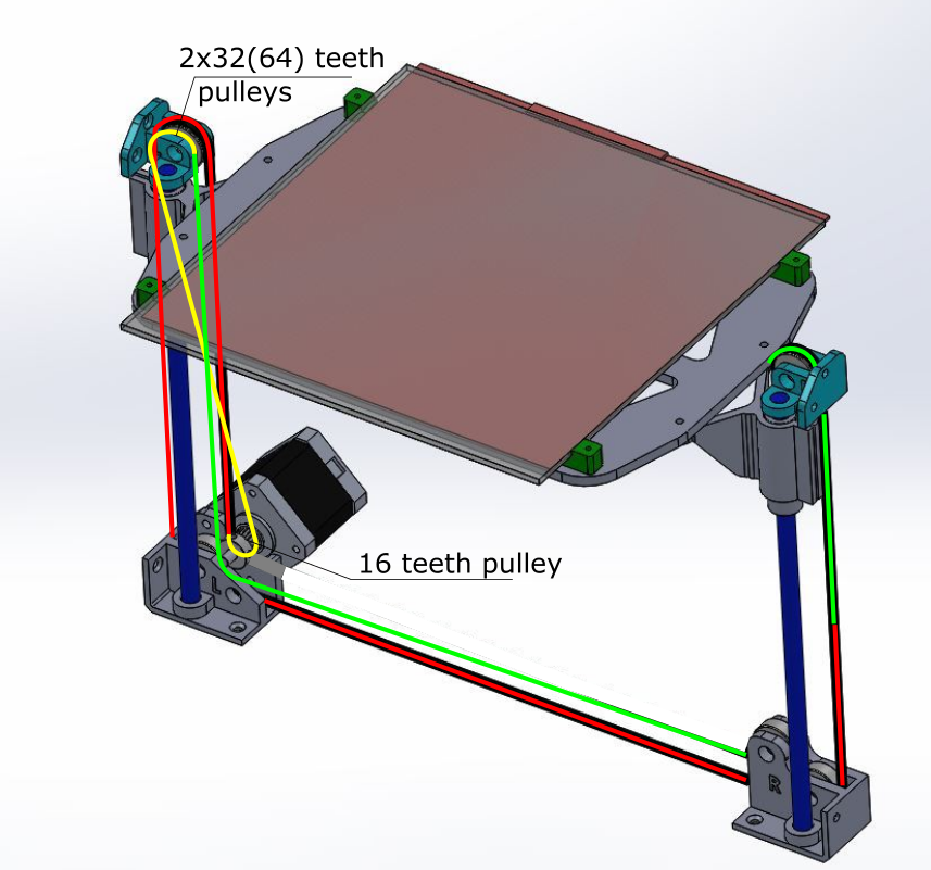
It should be pretty easy to add a second pulley on the motor side of the belt-Z design. I can see two improvements right away:
1) the double pulley will provide 2:1 reduction;
2) both pulleys can be 32 or 64 teeth pulleys and the motor one can be 16 teeth this will provide either another 2:1 or a 4:1 on top of the 2:1 provided by the compound pulley.
Hence a 4:1 or 8:1 reduction. That will throw you in the <0.05 per full step resolution for Z, with no microstepping.
The added benefit from turning the belt over the motor pulley and up is more teeth in contact on the motor side than in the original design.
@LarsK
I can't figure out how the belt is threaded around those pulleys without it being angled out of the parallel flow. Most compound pulleys examples I see are open loop, with one end constrained. This has to be a closed loop so that it can go in both directions. Can you show a better pic or a doodle?
Edited 3 time(s). Last edit at 11/19/2015 03:46PM by realthor.
RepRap Lander concept on Concept Forge
RepRap Lander concept on RepRap Forums
My Things, mostly experimental stuff
1) the double pulley will provide 2:1 reduction;
2) both pulleys can be 32 or 64 teeth pulleys and the motor one can be 16 teeth this will provide either another 2:1 or a 4:1 on top of the 2:1 provided by the compound pulley.
Hence a 4:1 or 8:1 reduction. That will throw you in the <0.05 per full step resolution for Z, with no microstepping.
The added benefit from turning the belt over the motor pulley and up is more teeth in contact on the motor side than in the original design.
@LarsK
Quote
LarsK
- A 2:1 reduction can be made by passing the belt around a set of pulleys. That can look like this
I can't figure out how the belt is threaded around those pulleys without it being angled out of the parallel flow. Most compound pulleys examples I see are open loop, with one end constrained. This has to be a closed loop so that it can go in both directions. Can you show a better pic or a doodle?
Edited 3 time(s). Last edit at 11/19/2015 03:46PM by realthor.
RepRap Lander concept on Concept Forge
RepRap Lander concept on RepRap Forums
My Things, mostly experimental stuff
|
Re: Best Z-axis configuration? November 19, 2015 03:44PM |
Registered: 9 years ago Posts: 346 |
Quote
realthor
It should be pretty easy to add a second pulley on the motor side of the belt-Z design. I can see two improvements right away:
1) the double pulley will provide 2:1 reduction;
2) both pulleys can be 32 or 64 teeth pulleys and the motor one can be 16 teeth this will provide either another 2:1 or a 4:1 on top of the 2:1 provided by the compound pulley.
Hence a 4:1 or 8:1 reduction. That will throw you in the <0.05 per full step resolution for Z, with no microstepping.
The added benefit from turning the belt over and up is more contact
.....
For the above - I understand now where you want to go, but I am pretty sure that a geared stepper or a higher current stepper with a driver that handles high amp and using microsteps would give better results.
But it would be interesting to test.
As for my drive - it is just a compound with both ends fixed ( open belt) and a tensioning idler at the motor.
Sketch attached.
Edited 1 time(s). Last edit at 11/19/2015 03:45PM by LarsK.
|
Re: Best Z-axis configuration? November 19, 2015 03:56PM |
Registered: 9 years ago Posts: 1,035 |
Thanks for the sketch. I understand now. I thought it was a closed loop that has been somehow compounded but with belt that is difficult to obtain, if at all.
With spectra it would be trivial if it wasn't for the need to wind it up on the motor shaft/bobbin to get enough friction as to not slip but that introduces string walking and another set of problems.
This could be very easily achieved with synchromesh though, but I don't like the idea of a single manufacturer with no easy ways to order/obtain, and repraps in theory try to reduce the number of specialized parts.
Edited 2 time(s). Last edit at 11/19/2015 07:40PM by realthor.
RepRap Lander concept on Concept Forge
RepRap Lander concept on RepRap Forums
My Things, mostly experimental stuff
|
Re: Best Z-axis configuration? November 20, 2015 06:17AM |
Registered: 10 years ago Posts: 179 |
Quote
J-Max
I awnsered about micro-stepping earlyer. The Z0 is set upon Zmin and is repeatable.Quote
Edvardas
What microstepping is used on Z-axis? What is the problem with current 0.2mm per step setup? Is Z0 easy to set and repeatable?
I could redesign AndreasL design on solidworks to be used for 2020 profiles and make it all beefier. I would also use 624 bearings for idlers as its size is almost the same as 20T GT2 pulley. Or do you know an European supplier of GT2 idler pulleys? Actually on AndreasL design only one idler pulley would be needed as the rest of idlers run on non-toothed side of belt.
The bed level is set manualy so you've got the right distance anywhere on the bed.
I thought 20T pulley's pitch was 12.73mm, so there's no perfect match for 20T (between 604 and 624).
On the version I'm working on, I used 16T pulleys (smaller diameter = better torque) and use 2xF623ZZ bearings are idler pulleys.
We can get perfect idler pulleys but its more expensive than bearings. And bearings works just fine.
They're pretty close to the GT2 16T (0.1mm delta in radius) and it's mostly a constant pitch diameter. For the tooth side of the belt, I use regular GT2 pulleys between MF105ZZ bearings.
++JM
But you do not have an adjustable bolt that touches an endstop at Z0? It is used (on both my prusa i3 and corexy) to alter a distance between a nozzle and a bed without having to touch the leveling screws. And it is quite handy as different materials like different distances between a nozzle and a bed for the first layer.
To use it one needs a very high resolution on Z axis which is achievable only with leadscrews and not the belts.
Can you post a picture on how you mount a GT2 pulley between MF105ZZ bearings to make a toothed idler out of it?
|
Re: Best Z-axis configuration? November 20, 2015 09:02AM |
Registered: 9 years ago Posts: 722 |
Hi guys 
Sure ! Here's the mount (with 625 2RS this time but I upgraded to MF105zz recently for the Z axis) :
Don't juge on the print quality, those prototype parts was printed with cheap filament at 220mm.s
That's what I get @ 120mm.s :
I had an adjustable scew for the Zmin endstop on my prusa I3. But you don't realy need one.
You setup your bed flat at the expected distance from your nozzle once. That's all.
Then it's easier to use different slicing parameters if you need to.
Actualy, when I get a special filament, I run some extrusion test (thin wall, temperature) and I save adjusted parameters.
I printed 6 different materials : ABS, Ninjaflex, PLA, Nylon, HIPS and Tribo with pretty good results.
I had to change temperature, extrusion flow, but never needed a custom first layer height.
I don't need to adjust the endstop or the bed until I change the hotend (or the nozzle).
Hopefully my printer don't need frequent calibration now.
++JM
Edited 1 time(s). Last edit at 11/20/2015 09:07AM by J-Max.
Sure ! Here's the mount (with 625 2RS this time but I upgraded to MF105zz recently for the Z axis) :

Don't juge on the print quality, those prototype parts was printed with cheap filament at 220mm.s
That's what I get @ 120mm.s :

Resolution for the Z axis is only about layer height. Why would you like to offset first layer ?Quote
Edvardas
But you do not have an adjustable bolt that touches an endstop at Z0? It is used (on both my prusa i3 and corexy) to alter a distance between a nozzle and a bed without having to touch the leveling screws. And it is quite handy as different materials like different distances between a nozzle and a bed for the first layer.
To use it one needs a very high resolution on Z axis which is achievable only with leadscrews and not the belts.
I had an adjustable scew for the Zmin endstop on my prusa I3. But you don't realy need one.
You setup your bed flat at the expected distance from your nozzle once. That's all.
Then it's easier to use different slicing parameters if you need to.
Actualy, when I get a special filament, I run some extrusion test (thin wall, temperature) and I save adjusted parameters.
I printed 6 different materials : ABS, Ninjaflex, PLA, Nylon, HIPS and Tribo with pretty good results.
I had to change temperature, extrusion flow, but never needed a custom first layer height.
I don't need to adjust the endstop or the bed until I change the hotend (or the nozzle).
Hopefully my printer don't need frequent calibration now.
++JM
Edited 1 time(s). Last edit at 11/20/2015 09:07AM by J-Max.
|
Re: Best Z-axis configuration? November 21, 2015 07:38PM |
Registered: 9 years ago Posts: 1,035 |
Maybe we could use both belt and spectra for what they are good at. Belt for motion transmission from the motor and spectra for easy routing through a system of pulleys.
@LarsK: Could your design be multiplied laterally (with spectra that is) so that the achieved reduction could be much higher?
Edited 15 time(s). Last edit at 11/22/2015 03:00PM by realthor.
RepRap Lander concept on Concept Forge
RepRap Lander concept on RepRap Forums
My Things, mostly experimental stuff
|
Re: Best Z-axis configuration? November 23, 2015 11:48AM |
Registered: 9 years ago Posts: 346 |
Quote
realthor
Maybe we could use both belt and spectra for what they are good at. Belt for motion transmission from the motor and spectra for easy routing through a system of pulleys.
@LarsK: Could your design be multiplied laterally (with spectra that is) so that the achieved reduction could be much higher?
Technologically we (as in mankind - general industry) abandoned this kind of gearing many years ago in favor of gear boxes - And these days we move towards direct drives. Compound systems only remain widely in use on cranes. And on those they are just used because it is inconvenient to handle steel cables with the kind of diameter required otherwise.
Crane doing heavy kiln shell lift
I am not sure how to handle the gearbox backlash, yet I feel fairly confident in saying that more power should be found in either gears or bigger motors, not wrapped belts or lines. Even I am looking towards removing the 2:1 used on my CoreXY's.
|
Re: Best Z-axis configuration? November 23, 2015 12:35PM |
Registered: 9 years ago Posts: 1,035 |
Quote
LarsK
Quote
realthor
Maybe we could use both belt and spectra for what they are good at. Belt for motion transmission from the motor and spectra for easy routing through a system of pulleys.
@LarsK: Could your design be multiplied laterally (with spectra that is) so that the achieved reduction could be much higher?
Technologically we (as in mankind - general industry) abandoned this kind of gearing many years ago in favor of gear boxes - And these days we move towards direct drives. Compound systems only remain widely in use on cranes. And on those they are just used because it is inconvenient to handle steel cables with the kind of diameter required otherwise.
Crane doing heavy kiln shell lift
I am not sure how to handle the gearbox backlash, yet I feel fairly confident in saying that more power should be found in either gears or bigger motors, not wrapped belts or lines. Even I am looking towards removing the 2:1 used on my CoreXY's.
Fair enough, I agree completely. My only grievance is that we can't do much with printing reliable gearboxes, as the plastic parts are very prone to plastic deformation and quick wear resulting in an ever increasing backlash that can't be linearly compensated for in software. And we will add yet another vitamin to the less and less replicable components. This might not be an issue with most reprappers though.
RepRap Lander concept on Concept Forge
RepRap Lander concept on RepRap Forums
My Things, mostly experimental stuff
|
Re: Best Z-axis configuration? November 23, 2015 01:03PM |
Registered: 9 years ago Posts: 346 |
Quote
realthor
Quote
LarsK
Quote
realthor
Maybe we could use both belt and spectra for what they are good at. Belt for motion transmission from the motor and spectra for easy routing through a system of pulleys.
@LarsK: Could your design be multiplied laterally (with spectra that is) so that the achieved reduction could be much higher?
Technologically we (as in mankind - general industry) abandoned this kind of gearing many years ago in favor of gear boxes - And these days we move towards direct drives. Compound systems only remain widely in use on cranes. And on those they are just used because it is inconvenient to handle steel cables with the kind of diameter required otherwise.
Crane doing heavy kiln shell lift
I am not sure how to handle the gearbox backlash, yet I feel fairly confident in saying that more power should be found in either gears or bigger motors, not wrapped belts or lines. Even I am looking towards removing the 2:1 used on my CoreXY's.
Fair enough, I agree completely. My only grievance is that we can't do much with printing reliable gearboxes, as the plastic parts are very prone to plastic deformation and quick wear resulting in an ever increasing backlash that can't be linearly compensated for in software. And we will add yet another vitamin to the less and less replicable components. This might not be an issue with most reprappers though.
Yes, more work is needed for sure. Many of the more advanced Makers are looking into printing Nylon which would solve the wear problem - And some of the best printers combined with strong designs that mitigate gear variations and soon we will be there - I hope
|
Re: Best Z-axis configuration? November 23, 2015 03:23PM |
Registered: 9 years ago Posts: 1,035 |
For no-gearbox belt/spectra solution the leadscrews are the way to go. Even Smartrap Corexy adopters have switched to leadscrews. AndreasL's is a good alternative for entry-level printers. But eventually I think everybody will switch to leadscrews as they reinforce the rigidity of their frame and expect ever better parts.
Also if electronics are going to allow faster and faster speeds the box sturdyness has to be spot-on, so installing leadscrews for Z will not be so difficult to achieve. Now let's print leadscrews
RepRap Lander concept on Concept Forge
RepRap Lander concept on RepRap Forums
My Things, mostly experimental stuff
|
Re: Best Z-axis configuration? November 23, 2015 03:25PM |
Registered: 9 years ago Posts: 722 |
|
Re: Best Z-axis configuration? November 23, 2015 05:16PM |
Registered: 9 years ago Posts: 1,035 |
Quote
J-Max
Hi guys,
Did you ever tryed the Igus Tribo filament ?
In many ways it seems better than nylon to me.
++JM
You might look into this thread at Ultimaker forums, it looks like a great option for enclosed printers and high temp (250ish hotend/110ish bed). It should be perfect for some gearbox parts that run smooth, like round toothed gears. I am thinking about minimizing wear so smooth tooth profile are the ones that come to mind.
The perfect backlash-free gearbox that I'd try with this material or nylon is a re-design of the harmonic hyperdrive that OskarPuzzle youtube user presented quite recently. Here's an image of the thing:

It doesn't use any flexible drum and looks veeery printable. Having a design that minimizes the number of teeth for our specific application so that it is less intricate and also improving on friction and the way the parts mate with each other would give us one of best options in terms of backlash-free plastic gearboxes for Z movement -where wear will be even more reduced by the infrequent actual movements. Throw the parts in a (yet to be created) mass-electroplating -otherwise called electroforming- bath (they can achieve up to 10mm in thickness in some applications, for us a 1mm would be enough I guess) and you have parts that can also withstand the plastic deformation due to constant pressure against the teeth of the gears. I am allowed to dream !! allright?
Edited 3 time(s). Last edit at 11/24/2015 06:10AM by realthor.
RepRap Lander concept on Concept Forge
RepRap Lander concept on RepRap Forums
My Things, mostly experimental stuff
|
Re: Best Z-axis configuration? November 24, 2015 03:11AM |
Registered: 9 years ago Posts: 722 |
|
Re: Best Z-axis configuration? November 24, 2015 06:32AM |
Registered: 9 years ago Posts: 346 |
Being an expat in Brazil it is difficult to get those kind of filaments in to the country  It is only really practical to order it to friend or family in EU and then bring it when traveling. Parcels customs takes months and tax+fees are substantial. Even they might think that the filament is for commercial purpose and hold it back entirely.
The specifications looks very nice though. Definitely something to look into some day
It is only really practical to order it to friend or family in EU and then bring it when traveling. Parcels customs takes months and tax+fees are substantial. Even they might think that the filament is for commercial purpose and hold it back entirely. The specifications looks very nice though. Definitely something to look into some day
|
Re: Best Z-axis configuration? November 24, 2015 03:50PM |
Registered: 9 years ago Posts: 722 |
Hi guys,
LarsK, Igus is an international company that sales diectly through their website to anybody in each country
See link below, local contact is on the upper right corner
[www.igus.com.br]
++JM
LarsK, Igus is an international company that sales diectly through their website to anybody in each country
See link below, local contact is on the upper right corner
[www.igus.com.br]
++JM
|
Re: Best Z-axis configuration? December 05, 2015 05:32AM |
Registered: 10 years ago Posts: 236 |


|
Re: Best Z-axis configuration? December 05, 2015 05:48AM |
Registered: 9 years ago Posts: 1,035 |
This is very interesting for two reasons: 1) I like the compound pulley that doubles the resolution and 2) I would have never thought that this solution would not bind.
There is also something that I don't quite like and that is the height of the slider, which is the same as it was if it were the usual on side lift. I would have thought that if you support the bed from 3 points you would be able to only use on single linear bearing on each rod so that you could gain some more Z height.
Nevertheless thanks for pointing me to it, it's a good concept to study.
RepRap Lander concept on Concept Forge
RepRap Lander concept on RepRap Forums
My Things, mostly experimental stuff
|
Re: Best Z-axis configuration? December 06, 2015 10:23AM |
Registered: 10 years ago Posts: 67 |
Quote
realthor
This is very interesting for two reasons: 1) I like the compound pulley that doubles the resolution and 2) I would have never thought that this solution would not bind.
There is also something that I don't quite like and that is the height of the slider, which is the same as it was if it were the usual on side lift. I would have thought that if you support the bed from 3 points you would be able to only use on single linear bearing on each rod so that you could gain some more Z height.
Nevertheless thanks for pointing me to it, it's a good concept to study.
You do realize that this design removes the problem that an unpowered motor drops the bed?
"Never argue with stupid people, they will drag you down to their level and then beat you with experience."
|
Re: Best Z-axis configuration? December 06, 2015 11:21AM |
Registered: 10 years ago Posts: 236 |
|
Re: Best Z-axis configuration? December 06, 2015 12:42PM |
Registered: 9 years ago Posts: 1,035 |
Quote
fabrice974
no
if power go off, the bed still drop
if you don't have reliable electricity, you can use an inverter / ups
You do seem to have this or at least I hope so because I would like to see it moving. Do you have any video or link with this setup performing some homing of Z or some autocalibration? It would be interesting to see the bed move some weight on the outer edge opposite to the motor.
RepRap Lander concept on Concept Forge
RepRap Lander concept on RepRap Forums
My Things, mostly experimental stuff
|
Re: Best Z-axis configuration? December 06, 2015 01:13PM |
Registered: 10 years ago Posts: 236 |
i made a quick video
[www.youtube.com]
will make other soon
how much weight do you want to see it moving?
[www.youtube.com]
will make other soon
how much weight do you want to see it moving?
|
Re: Best Z-axis configuration? December 06, 2015 01:42PM |
Registered: 9 years ago Posts: 1,035 |
Great concept, it is similar with Larsk's fro the previous posts and I am sure I've seen this before on youtube. About the weight I am mainly concerned about binding in the vertical linear bearings because the linear slides would be in between the motor and the weight. So if the motor pulls up for example and the weight (0.5kg, dunno, don't think it's important but if you put more weight you would probably see binding that would otherwise be imperceptible yet you would see its results in the print), so the weight would press down, creating a flipping force around the axis defined by the vertical rods.
I hope I am making some sense here. Actually the binding would only happen when you would lift the bed and the weight of the printed part (or the bed in general) would fall outside the axis delimited by the Z rods. This will happen only if you use Z-lift (not retraction).
Try to simulate the Z lift (short bursts of accelerated lift) with let's say 0,5-1kg on the outer edge and observe how the bearings behave. I don't know though if this will be observable. I don't really know if this is the case, it's only my concern.
Edited 1 time(s). Last edit at 12/06/2015 01:44PM by realthor.
RepRap Lander concept on Concept Forge
RepRap Lander concept on RepRap Forums
My Things, mostly experimental stuff
|
Re: Best Z-axis configuration? December 07, 2015 04:01PM |
Registered: 9 years ago Posts: 31 |
What about a compound approach-- use a single leadscrew + linear guide to actuate an effector to which three cables are fixed. A system of pulleys could then be used to transfer the motion along this single lead screw to support three points on the bed. This way you would get the benefits of a single lead screw without the downsides of cantilevering.


Sorry, only registered users may post in this forum.