Home
>
Reprappers
>
Topic
Folger Y End Stop Position
Posted by Vanbot
|
Folger Y End Stop Position April 17, 2015 01:07AM |
Registered: 9 years ago Posts: 156 |
In the FT manual it shows the microswitch for the Y end stop contacting the linear bearing holder. My kit doesn't have a linear bearing holder as the bearing is just zip tied directly to the underside of the bed support. This means that if I install my end stop the way the manual shows it won't contact anything. The only way I can get it to work the way it is currently set up is to have it contact the screw that protrudes through the right-front corner of the heat bed. But because that is very close to the front of the printer frame, the effective print area of the printer is reduced by about 140 sq cm.
How are others setting up their Y end stops?
How are others setting up their Y end stops?
|
Re: Folger Y End Stop Position April 17, 2015 01:18AM |
Registered: 9 years ago Posts: 21 |
Check out Folger Prusa Bible(ish). There is a wealth of information on there. Specifically you'll want to check out the Folger thread started a long time ago. Folger Thread. This thread helped me immensely throughout my build and upgrades! I printed out a different endstop for mine after I got it up and running initially, but from what my old memory serves, guys had a lot of luck attaching the endstop to the long 8mm threaded rod at the end closest to you. The corner of the bed will catch it. Have fun!
|
Re: Folger Y End Stop Position April 17, 2015 01:31AM |
Registered: 9 years ago Posts: 156 |
Thanks Enzo. I'm deep into the Folger thread and used the Folger manuals for my build.
But what I'm particularly looking for is the way people have set up their Y end stops so that the microswitch contacts the bare bearing. This is obviously only going to be the case in kits where there was no linear bearing holders on the Y carriage which is the case with mine.
But what I'm particularly looking for is the way people have set up their Y end stops so that the microswitch contacts the bare bearing. This is obviously only going to be the case in kits where there was no linear bearing holders on the Y carriage which is the case with mine.
|
Re: Folger Y End Stop Position April 17, 2015 10:48PM |
Registered: 9 years ago Posts: 21 |
Quote
Vanbot
Thanks Enzo. I'm deep into the Folger thread and used the Folger manuals for my build.
But what I'm particularly looking for is the way people have set up their Y end stops so that the microswitch contacts the bare bearing. This is obviously only going to be the case in kits where there was no linear bearing holders on the Y carriage which is the case with mine.
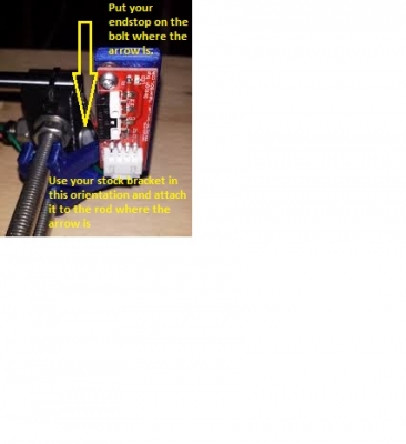
Of course I couldn't find the picture I was looking for, so I found something similar and made a note in paint. It's not the same bracket obviously, but the mounting style is similar as far as it being vertical goes. Hope this helps! It won't actually contact the bearing, but instead hit roughly the corner of the print bed where your leveling spring is. You'll still maintain your 200mm of travel as well

Edited 1 time(s). Last edit at 04/17/2015 10:49PM by enzo1027.
|
Re: Folger Y End Stop Position April 18, 2015 01:03AM |
Registered: 9 years ago Posts: 156 |
Quote
enzo1027
[attachment 53079 images.jpg]Quote
Vanbot
Thanks Enzo. I'm deep into the Folger thread and used the Folger manuals for my build.
But what I'm particularly looking for is the way people have set up their Y end stops so that the microswitch contacts the bare bearing. This is obviously only going to be the case in kits where there was no linear bearing holders on the Y carriage which is the case with mine.
Of course I couldn't find the picture I was looking for, so I found something similar and made a note in paint. It's not the same bracket obviously, but the mounting style is similar as far as it being vertical goes. Hope this helps! It won't actually contact the bearing, but instead hit roughly the corner of the print bed where your leveling spring is. You'll still maintain your 200mm of travel as well
Nice! Very helpful Enzo. Thank-you for that.
|
Re: Folger Y End Stop Position April 18, 2015 08:44AM |
Registered: 9 years ago Posts: 116 |
That mount shown above isn't in the kit.
Like I said in another thread Dan told me to mount it on the extra bit of threaded rod sticking out the back which I did but you should mount it on the power supply side of the frame where it won't get caught by the heated bed wires. Tilt to the side to go under the heated bed and it can be actuated by the heated bed support frame. I inverted the Y motor cable as well to get the motor homing in the correct direction. I have done a dry print but haven't extruded any material yet.
Like I said in another thread Dan told me to mount it on the extra bit of threaded rod sticking out the back which I did but you should mount it on the power supply side of the frame where it won't get caught by the heated bed wires. Tilt to the side to go under the heated bed and it can be actuated by the heated bed support frame. I inverted the Y motor cable as well to get the motor homing in the correct direction. I have done a dry print but haven't extruded any material yet.
|
Re: Folger Y End Stop Position April 18, 2015 11:57AM |
Registered: 9 years ago Posts: 21 |
Quote
Ecky
That mount shown above isn't in the kit.
Like I said in another thread Dan told me to mount it on the extra bit of threaded rod sticking out the back which I did but you should mount it on the power supply side of the frame where it won't get caught by the heated bed wires. Tilt to the side to go under the heated bed and it can be actuated by the heated bed support frame. I inverted the Y motor cable as well to get the motor homing in the correct direction. I have done a dry print but haven't extruded any material yet.
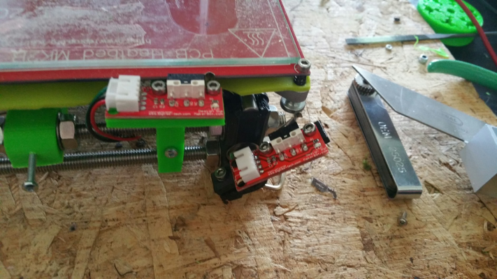
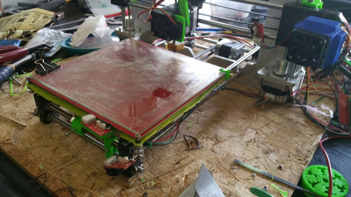
Sorry, I was at work last night. I took my old end stop out and mounted it to show you! This is what I was trying to show you. The end stop functions, in my humble opinion, better in the front of the machine than the rear. The only difference is you invert your end stop(or change your wiring back to stock) in the firmware. It allows you the full 200mm of travel. It also keeps all the wires. Out of the way. Hope this helps!
Edited 1 time(s). Last edit at 04/18/2015 12:02PM by enzo1027.
|
Re: Folger Y End Stop Position April 18, 2015 07:45PM |
Registered: 9 years ago Posts: 116 |
I have the end stop tilted the other way and it contacts the hot plate carrier on the X face under the hot plate/heat bed. When homed the extruder nozzle is hanging in the air.
WOW you went to a lot of trouble painting the frame gray.
Edited 1 time(s). Last edit at 04/18/2015 07:49PM by Ecky.
WOW you went to a lot of trouble painting the frame gray.

Edited 1 time(s). Last edit at 04/18/2015 07:49PM by Ecky.
Sorry, only registered users may post in this forum.


