Folger Tech 2020 i3 Printer Kit (Official Thread)
Posted by Dan_FolgerTech
|
Re: Folger Tech 2020 i3 Printer Kit (Official Thread) October 14, 2015 02:47PM |
Registered: 8 years ago Posts: 84 |
|
Re: Folger Tech 2020 i3 Printer Kit (Official Thread) October 14, 2015 03:10PM |
Registered: 8 years ago Posts: 541 |
Quote
woodknack
Quote
tjnamtiw
I'm on the fence with this one. Clearly you are one of the more knowledgeable gurus here so I respect your opinion. The Z axis is the least used axis as far as cycles go. Yes, movement must be accurate to have accurate layer thicknesses. However, the lowly threaded rod, once calibrated, should yield accurate movement. The X carriage and extruder assembly all hang on the Z threaded rods, so there's no backlash or looseness there since the nuts are always being pushed down against the threads. What are the real advantages of using the lead screws other than it looks more professional?
You are only thinking about one direction. You get backlash when you axis (Z for this instance) changes direction. In the beginning the nut and threaded rods will probably work fine as they are still tight. But over time the rod and nut will start to ware and this is when the backlash issue will happen. Thats why people made a double nut with a spring for the z axis like this one on thingiverse, z-anti backlash. Plus this is a kit printer. By improving it we get a better machine and more knowledge. Plus its just plain fun to tinker. Speaking of tinkering, how is TINKERCAD working for you?
I understand that when you change direction, the backlash comes into play BUT the Z axis never changes direction during a print. It's always moving up a step at a time. At least with the things I've printed.
Oh, yea, TINKERCAD is awesome for an easy to use program. I'm using it every day to modify things, combine things, invent new things, change wording on trophies for the grand kids, and even today I printed out a power window knob for the son's Jeep! I only wish it had the ability to easily chamfer or radius edges. Even rounding the corners of a square is a chore. There's no template for that. To that end I'm also learning AutoCad's free 123Design. I've used AutoCad from day one but never got into 3 D.
I fully understand the urge to tinker and improve. I'm a sucker for anything technological. Always have been for 72 years.
 I can program PLC'S in ladder logic and code, can program robots, design products, fly RC airplanes (60 years doing that), enjoy woodworking, am a part time potter and enjoy working on cars. Other than that, I just sit around and do nothing!!!!! hahaha I'm sure I'll have those lead screws on here whether I need them or not just because they are cool and it gives me an excuse to print some more 'stuff'. My printer has been going since 7 am printing 'stuff' for Halloween plus an X motor cooling shroud I designed with TINKERCAD. That's the only motor that gets hot and it has the lowest voltage by far. I read the specs on our stepsticks and it appears that they can only put out a max of 1.5 amps so anything goes. That's assuming FT hasn't changed them.
 Was it you that wanted pictures of the latest version of the FT extruder drive? If so, I'll get some tonight.
|
Re: Folger Tech 2020 i3 Printer Kit (Official Thread) October 14, 2015 03:55PM |
Registered: 8 years ago Posts: 99 |
Quote
tjnamtiw
Quote
woodknack
Quote
tjnamtiw
I'm on the fence with this one. Clearly you are one of the more knowledgeable gurus here so I respect your opinion. The Z axis is the least used axis as far as cycles go. Yes, movement must be accurate to have accurate layer thicknesses. However, the lowly threaded rod, once calibrated, should yield accurate movement. The X carriage and extruder assembly all hang on the Z threaded rods, so there's no backlash or looseness there since the nuts are always being pushed down against the threads. What are the real advantages of using the lead screws other than it looks more professional?
You are only thinking about one direction. You get backlash when you axis (Z for this instance) changes direction. In the beginning the nut and threaded rods will probably work fine as they are still tight. But over time the rod and nut will start to ware and this is when the backlash issue will happen. Thats why people made a double nut with a spring for the z axis like this one on thingiverse, z-anti backlash. Plus this is a kit printer. By improving it we get a better machine and more knowledge. Plus its just plain fun to tinker. Speaking of tinkering, how is TINKERCAD working for you?
I understand that when you change direction, the backlash comes into play BUT the Z axis never changes direction during a print. It's always moving up a step at a time. At least with the things I've printed.
Oh, yea, TINKERCAD is awesome for an easy to use program. I'm using it every day to modify things, combine things, invent new things, change wording on trophies for the grand kids, and even today I printed out a power window knob for the son's Jeep! I only wish it had the ability to easily chamfer or radius edges. Even rounding the corners of a square is a chore. There's no template for that. To that end I'm also learning AutoCad's free 123Design. I've used AutoCad from day one but never got into 3 D.
I fully understand the urge to tinker and improve. I'm a sucker for anything technological. Always have been for 72 years.
Was it you that wanted pictures of the latest version of the FT extruder drive? If so, I'll get some tonight.
I too have been using 123d. But I find myself going back to tinkercad for easy tasks. I need to stick with 123d until I find it easy.
|
Re: Folger Tech 2020 i3 Printer Kit (Official Thread) October 14, 2015 06:41PM |
Registered: 8 years ago Posts: 33 |
Quote
tjnamtiw
Quote
woodknack
Quote
tjnamtiw
I'm on the fence with this one. Clearly you are one of the more knowledgeable gurus here so I respect your opinion. The Z axis is the least used axis as far as cycles go. Yes, movement must be accurate to have accurate layer thicknesses. However, the lowly threaded rod, once calibrated, should yield accurate movement. The X carriage and extruder assembly all hang on the Z threaded rods, so there's no backlash or looseness there since the nuts are always being pushed down against the threads. What are the real advantages of using the lead screws other than it looks more professional?
You are only thinking about one direction. You get backlash when you axis (Z for this instance) changes direction. In the beginning the nut and threaded rods will probably work fine as they are still tight. But over time the rod and nut will start to ware and this is when the backlash issue will happen. Thats why people made a double nut with a spring for the z axis like this one on thingiverse, z-anti backlash. Plus this is a kit printer. By improving it we get a better machine and more knowledge. Plus its just plain fun to tinker. Speaking of tinkering, how is TINKERCAD working for you?
I got my 8mm threaded rods from bangood and they were pretty good looking, i noticed some lateral movement and backlash which i did not like. I put the long small end of the nuts into the 3 jaw chuck on the lathe and kept crimping them until all lateral movement and backlash was gone. I use 20W50 synthetic oil (harley oil) on them and so far it is still solid. I have used 1 1/2 rolls of abs through it since i installed them and all is good. Now I am not letting the weight of the z carrage be held by the motors and adding load to the motor bearings and the spring action of the couplings I turned the end of the rod down to 5mm and used a bearing in a remade z rod support.
I understand that when you change direction, the backlash comes into play BUT the Z axis never changes direction during a print. It's always moving up a step at a time. At least with the things I've printed.
If you have it set to lift as it crosses over you tell it how much to lift and then it goes bach to its correct hight when it starts back. I was using petg and getting alot of strings , i believe it was therippa who told me to change the settings and give it some lift , i set it to 3mm and no more problem. So depends on your settings it will go up and down both during a print.
Oh, yea, TINKERCAD is awesome for an easy to use program. I'm using it every day to modify things, combine things, invent new things, change wording on trophies for the grand kids, and even today I printed out a power window knob for the son's Jeep! I only wish it had the ability to easily chamfer or radius edges. Even rounding the corners of a square is a chore. There's no template for that. To that end I'm also learning AutoCad's free 123Design. I've used AutoCad from day one but never got into 3 D.
I fully understand the urge to tinker and improve. I'm a sucker for anything technological. Always have been for 72 years.
Was it you that wanted pictures of the latest version of the FT extruder drive? If so, I'll get some tonight.
|
Re: Folger Tech 2020 i3 Printer Kit (Official Thread) October 14, 2015 07:19PM |
Registered: 8 years ago Posts: 99 |
Hey KN4UD.........
Good idea for tightening up the nut on your lathe chuck. If mine are like that, I'll do the same on my lathe. I had a small cnc mill a few years ago that had a brass lead screw nut that was split on one side and had a screw going from one side to the other on the bottom of the nut. If you started to get back lash you could just tighten the nut a little.
Do you have pictures of your z bearing support you made?
Edited 1 time(s). Last edit at 10/14/2015 07:21PM by woodknack.
|
Re: Folger Tech 2020 i3 Printer Kit (Official Thread) October 14, 2015 07:27PM |
Registered: 8 years ago Posts: 541 |
Quote
woodknack
Quote
tjnamtiw
Quote
woodknack
Quote
tjnamtiw
I'm on the fence with this one. Clearly you are one of the more knowledgeable gurus here so I respect your opinion. The Z axis is the least used axis as far as cycles go. Yes, movement must be accurate to have accurate layer thicknesses. However, the lowly threaded rod, once calibrated, should yield accurate movement. The X carriage and extruder assembly all hang on the Z threaded rods, so there's no backlash or looseness there since the nuts are always being pushed down against the threads. What are the real advantages of using the lead screws other than it looks more professional?
You are only thinking about one direction. You get backlash when you axis (Z for this instance) changes direction. In the beginning the nut and threaded rods will probably work fine as they are still tight. But over time the rod and nut will start to ware and this is when the backlash issue will happen. Thats why people made a double nut with a spring for the z axis like this one on thingiverse, z-anti backlash. Plus this is a kit printer. By improving it we get a better machine and more knowledge. Plus its just plain fun to tinker. Speaking of tinkering, how is TINKERCAD working for you?
I understand that when you change direction, the backlash comes into play BUT the Z axis never changes direction during a print. It's always moving up a step at a time. At least with the things I've printed.
Oh, yea, TINKERCAD is awesome for an easy to use program. I'm using it every day to modify things, combine things, invent new things, change wording on trophies for the grand kids, and even today I printed out a power window knob for the son's Jeep! I only wish it had the ability to easily chamfer or radius edges. Even rounding the corners of a square is a chore. There's no template for that. To that end I'm also learning AutoCad's free 123Design. I've used AutoCad from day one but never got into 3 D.
I fully understand the urge to tinker and improve. I'm a sucker for anything technological. Always have been for 72 years.
Was it you that wanted pictures of the latest version of the FT extruder drive? If so, I'll get some tonight.
I too have been using 123d. But I find myself going back to tinkercad for easy tasks. I need to stick with 123d until I find it easy.
Yea, it's almost too easy and spoils you!
|
Re: Folger Tech 2020 i3 Printer Kit (Official Thread) October 14, 2015 07:29PM |
Registered: 8 years ago Posts: 541 |
Quote
kn4ud
Quote
tjnamtiw
Quote
woodknack
Quote
tjnamtiw
I'm on the fence with this one. Clearly you are one of the more knowledgeable gurus here so I respect your opinion. The Z axis is the least used axis as far as cycles go. Yes, movement must be accurate to have accurate layer thicknesses. However, the lowly threaded rod, once calibrated, should yield accurate movement. The X carriage and extruder assembly all hang on the Z threaded rods, so there's no backlash or looseness there since the nuts are always being pushed down against the threads. What are the real advantages of using the lead screws other than it looks more professional?
You are only thinking about one direction. You get backlash when you axis (Z for this instance) changes direction. In the beginning the nut and threaded rods will probably work fine as they are still tight. But over time the rod and nut will start to ware and this is when the backlash issue will happen. Thats why people made a double nut with a spring for the z axis like this one on thingiverse, z-anti backlash. Plus this is a kit printer. By improving it we get a better machine and more knowledge. Plus its just plain fun to tinker. Speaking of tinkering, how is TINKERCAD working for you?
I got my 8mm threaded rods from bangood and they were pretty good looking, i noticed some lateral movement and backlash which i did not like. I put the long small end of the nuts into the 3 jaw chuck on the lathe and kept crimping them until all lateral movement and backlash was gone. I use 20W50 synthetic oil (harley oil) on them and so far it is still solid. I have used 1 1/2 rolls of abs through it since i installed them and all is good. Now I am not letting the weight of the z carrage be held by the motors and adding load to the motor bearings and the spring action of the couplings I turned the end of the rod down to 5mm and used a bearing in a remade z rod support.
I understand that when you change direction, the backlash comes into play BUT the Z axis never changes direction during a print. It's always moving up a step at a time. At least with the things I've printed.
If you have it set to lift as it crosses over you tell it how much to lift and then it goes bach to its correct hight when it starts back. I was using petg and getting alot of strings , i believe it was therippa who told me to change the settings and give it some lift , i set it to 3mm and no more problem. So depends on your settings it will go up and down both during a print.
Oh, yea, TINKERCAD is awesome for an easy to use program. I'm using it every day to modify things, combine things, invent new things, change wording on trophies for the grand kids, and even today I printed out a power window knob for the son's Jeep! I only wish it had the ability to easily chamfer or radius edges. Even rounding the corners of a square is a chore. There's no template for that. To that end I'm also learning AutoCad's free 123Design. I've used AutoCad from day one but never got into 3 D.
I fully understand the urge to tinker and improve. I'm a sucker for anything technological. Always have been for 72 years.
Was it you that wanted pictures of the latest version of the FT extruder drive? If so, I'll get some tonight.
OK, I now understand that you could have movement up and down. Hmmmm, maybe it would help MY stringing. Gotta try it. At the rate I'm using this printer, I probably will have those threaded rods worn out soon anyway. I guess I better start printing the Z carriage pieces for the lead screws!
|
Re: Folger Tech 2020 i3 Printer Kit (Official Thread) October 14, 2015 08:11PM |
Registered: 8 years ago Posts: 99 |
Quote
tjnamtiw
Quote
kn4ud
Quote
tjnamtiw
Quote
woodknack
Quote
tjnamtiw
I'm on the fence with this one. Clearly you are one of the more knowledgeable gurus here so I respect your opinion. The Z axis is the least used axis as far as cycles go. Yes, movement must be accurate to have accurate layer thicknesses. However, the lowly threaded rod, once calibrated, should yield accurate movement. The X carriage and extruder assembly all hang on the Z threaded rods, so there's no backlash or looseness there since the nuts are always being pushed down against the threads. What are the real advantages of using the lead screws other than it looks more professional?
You are only thinking about one direction. You get backlash when you axis (Z for this instance) changes direction. In the beginning the nut and threaded rods will probably work fine as they are still tight. But over time the rod and nut will start to ware and this is when the backlash issue will happen. Thats why people made a double nut with a spring for the z axis like this one on thingiverse, z-anti backlash. Plus this is a kit printer. By improving it we get a better machine and more knowledge. Plus its just plain fun to tinker. Speaking of tinkering, how is TINKERCAD working for you?
I got my 8mm threaded rods from bangood and they were pretty good looking, i noticed some lateral movement and backlash which i did not like. I put the long small end of the nuts into the 3 jaw chuck on the lathe and kept crimping them until all lateral movement and backlash was gone. I use 20W50 synthetic oil (harley oil) on them and so far it is still solid. I have used 1 1/2 rolls of abs through it since i installed them and all is good. Now I am not letting the weight of the z carrage be held by the motors and adding load to the motor bearings and the spring action of the couplings I turned the end of the rod down to 5mm and used a bearing in a remade z rod support.
I understand that when you change direction, the backlash comes into play BUT the Z axis never changes direction during a print. It's always moving up a step at a time. At least with the things I've printed.
If you have it set to lift as it crosses over you tell it how much to lift and then it goes bach to its correct hight when it starts back. I was using petg and getting alot of strings , i believe it was therippa who told me to change the settings and give it some lift , i set it to 3mm and no more problem. So depends on your settings it will go up and down both during a print.
Oh, yea, TINKERCAD is awesome for an easy to use program. I'm using it every day to modify things, combine things, invent new things, change wording on trophies for the grand kids, and even today I printed out a power window knob for the son's Jeep! I only wish it had the ability to easily chamfer or radius edges. Even rounding the corners of a square is a chore. There's no template for that. To that end I'm also learning AutoCad's free 123Design. I've used AutoCad from day one but never got into 3 D.
I fully understand the urge to tinker and improve. I'm a sucker for anything technological. Always have been for 72 years.
Was it you that wanted pictures of the latest version of the FT extruder drive? If so, I'll get some tonight.
OK, I now understand that you could have movement up and down. Hmmmm, maybe it would help MY stringing. Gotta try it. At the rate I'm using this printer, I probably will have those threaded rods worn out soon anyway. I guess I better start printing the Z carriage pieces for the lead screws!
Too funny I was just looking for that on thingiverse. Can't seem to find it. Anyone have the link?
|
Re: Folger Tech 2020 i3 Printer Kit (Official Thread) October 14, 2015 08:44PM |
Registered: 8 years ago Posts: 33 |
Quote
woodknack
Hey KN4UD.........
Good idea for tightening up the nut on your lathe chuck. If mine are like that, I'll do the same on my lathe. I had a small cnc mill a few years ago that had a brass lead screw nut that was split on one side and had a screw going from one side to the other on the bottom of the nut. If you started to get back lash you could just tighten the nut a little.
Do you have pictures of your z bearing support you made?
[i.imgur.com]
This is a picture of the one I done in PETG. The ones I am using now are ABS. I gave some thought of making a split nut like the one you are talking about, It has been 20+ years since I cut a multi start internal thread (lol) so I just settled for crimping it. It is still good and checking it with a dial indicator it only has .0015 inch slack. I am going to do a remake of the upper support and use a 5mm bearing in it too and make a solid 5mm cupling from the motor to it to completely do away with the flex and sping of the factory cupling and the 5x8 one. I probably is not necessary but hay I love tinkering with this thing and trying to make it better, its fun. I added a 4th bearing to the bed because I could feel some twist in it. I have learned with these bearings to order alot of them and go through them to find the best ones last time I got 6 out of 10 that I found usable.
I am going to try and make pictures of the unit tomorrow and post them. I am 2hours into a 6hour print for the grand kids right now.
|
Re: Folger Tech 2020 i3 Printer Kit (Official Thread) October 14, 2015 09:10PM |
Registered: 8 years ago Posts: 268 |
Quote
therippa
Quote
awmyhr
That is a pretty awesome set up upgrades therippa! Could you point me to details on how to install/implement the auto-leveling? I saw a post way back where you linked to a thread/diagram in German, but that was not enough for me to follow. I'd really like to add this feature...
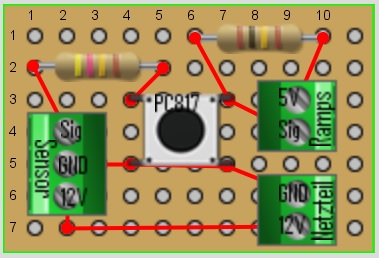
First you need to get an aluminum build plate, and this sensor
Then you need to build a circuit that handles the switch connection, since the probe runs on 12v, but the RAMPS board needs 5v. It's just this guy...
You need to order a 4k7 resistor and a 10k resistor, some terminal blocks, and a PC817 optocoupler, and wire it as it is in the diagram.
Once you get it all together, you can follow Tom's video on adding autoleveling/autotramming.
I bought everything I needed for auto tramming, however it doesn't appear I am running the correct Marlin Firmware!?!? What version are you running??
|
Re: Folger Tech 2020 i3 Printer Kit (Official Thread) October 14, 2015 10:14PM |
Registered: 8 years ago Posts: 276 |
Quote
sonnylowe
Quote
therippa
Quote
awmyhr
That is a pretty awesome set up upgrades therippa! Could you point me to details on how to install/implement the auto-leveling? I saw a post way back where you linked to a thread/diagram in German, but that was not enough for me to follow. I'd really like to add this feature...
First you need to get an aluminum build plate, and this sensor
Then you need to build a circuit that handles the switch connection, since the probe runs on 12v, but the RAMPS board needs 5v. It's just this guy...
You need to order a 4k7 resistor and a 10k resistor, some terminal blocks, and a PC817 optocoupler, and wire it as it is in the diagram.
Once you get it all together, you can follow Tom's video on adding autoleveling/autotramming.
I bought everything I needed for auto tramming, however it doesn't appear I am running the correct Marlin Firmware!?!? What version are you running??
Check my signature
Need help? Visit the Folgertech Wikia Page
The latest Marlin firmware with Folgertech Prusa i3 settings merged in, get it here
And check out my designs on Thingiverse, and follow me if you like what you see!
|
Re: Folger Tech 2020 i3 Printer Kit (Official Thread) October 14, 2015 10:24PM |
Registered: 8 years ago Posts: 430 |
Quote
built350camaro
Man I am really wanting to print this but no matter how I try I cant figure it out. I have split it into parts with cura but I cant figure out the best way to print it.
This
How about split it down the center of the long dimension and glue the two pieces together.
Newbie with Folgertech 2020 i3.
|
Re: Folger Tech 2020 i3 Printer Kit (Official Thread) October 14, 2015 10:33PM |
Registered: 8 years ago Posts: 268 |
Quote
therippa
Quote
sonnylowe
Quote
therippa
Quote
awmyhr
That is a pretty awesome set up upgrades therippa! Could you point me to details on how to install/implement the auto-leveling? I saw a post way back where you linked to a thread/diagram in German, but that was not enough for me to follow. I'd really like to add this feature...
First you need to get an aluminum build plate, and this sensor
Then you need to build a circuit that handles the switch connection, since the probe runs on 12v, but the RAMPS board needs 5v. It's just this guy...
You need to order a 4k7 resistor and a 10k resistor, some terminal blocks, and a PC817 optocoupler, and wire it as it is in the diagram.
Once you get it all together, you can follow Tom's video on adding autoleveling/autotramming.
I bought everything I needed for auto tramming, however it doesn't appear I am running the correct Marlin Firmware!?!? What version are you running??
Check my signature
You made it too easy ;-)
Thanks!!!
|
Re: Folger Tech 2020 i3 Printer Kit (Official Thread) October 14, 2015 11:46PM |
Registered: 8 years ago Posts: 268 |
Quote
sonnylowe
Quote
therippa
Quote
sonnylowe
Quote
therippa
Quote
awmyhr
That is a pretty awesome set up upgrades therippa! Could you point me to details on how to install/implement the auto-leveling? I saw a post way back where you linked to a thread/diagram in German, but that was not enough for me to follow. I'd really like to add this feature...
First you need to get an aluminum build plate, and this sensor
Then you need to build a circuit that handles the switch connection, since the probe runs on 12v, but the RAMPS board needs 5v. It's just this guy...
You need to order a 4k7 resistor and a 10k resistor, some terminal blocks, and a PC817 optocoupler, and wire it as it is in the diagram.
Once you get it all together, you can follow Tom's video on adding autoleveling/autotramming.
I bought everything I needed for auto tramming, however it doesn't appear I am running the correct Marlin Firmware!?!? What version are you running??
Check my signature
You made it too easy ;-)
Thanks!!!
Okay, I'm stuck...again :-(
I updated the firmware and uploaded it.
I followed Tom's guide to test the sensor and make sure the firmware was working properly (printer homes using the probe with no problem).
I give it a G29 command but nothing happens!?!?
I checked and rechecked the firmware, all of the auto leveling code matches yours except two things, the grid pattern (mine is different due to my sensor mount-left of the hot end in X-Axis) and I deleted the comment on:
#define ENABLE_AUTO_BED_LEVELING (your firmware has this commented out).
Any idea what I might be missing!?!?
Thanks,
Sonny
FYI: I did a cut and paste of the Auto Level portion of your config file, I did not want to upload the full file as I didn't want it to have to change other settings I had already tweaked...
|
Re: Folger Tech 2020 i3 Printer Kit (Official Thread) October 15, 2015 12:35AM |
Registered: 8 years ago Posts: 62 |
Quote
woodknack
Quote
tjnamtiw
Quote
woodknack
Quote
tjnamtiw
I'm on the fence with this one. Clearly you are one of the more knowledgeable gurus here so I respect your opinion. The Z axis is the least used axis as far as cycles go. Yes, movement must be accurate to have accurate layer thicknesses. However, the lowly threaded rod, once calibrated, should yield accurate movement. The X carriage and extruder assembly all hang on the Z threaded rods, so there's no backlash or looseness there since the nuts are always being pushed down against the threads. What are the real advantages of using the lead screws other than it looks more professional?
You are only thinking about one direction. You get backlash when you axis (Z for this instance) changes direction. In the beginning the nut and threaded rods will probably work fine as they are still tight. But over time the rod and nut will start to ware and this is when the backlash issue will happen. Thats why people made a double nut with a spring for the z axis like this one on thingiverse, z-anti backlash. Plus this is a kit printer. By improving it we get a better machine and more knowledge. Plus its just plain fun to tinker. Speaking of tinkering, how is TINKERCAD working for you?
I understand that when you change direction, the backlash comes into play BUT the Z axis never changes direction during a print. It's always moving up a step at a time. At least with the things I've printed.
Oh, yea, TINKERCAD is awesome for an easy to use program. I'm using it every day to modify things, combine things, invent new things, change wording on trophies for the grand kids, and even today I printed out a power window knob for the son's Jeep! I only wish it had the ability to easily chamfer or radius edges. Even rounding the corners of a square is a chore. There's no template for that. To that end I'm also learning AutoCad's free 123Design. I've used AutoCad from day one but never got into 3 D.
I fully understand the urge to tinker and improve. I'm a sucker for anything technological. Always have been for 72 years.
Was it you that wanted pictures of the latest version of the FT extruder drive? If so, I'll get some tonight.
I too have been using 123d. But I find myself going back to tinkercad for easy tasks. I need to stick with 123d until I find it easy.
Have you tried Fusion 360? They really do a good job updating the basic core of 123D!
Mr.Fus
<------------------------------------------------->
Green M3D (Running v.1.3.6.3Beta)
FolgerTech Prusa i3 (2020 Frame)
<------------------------------------------------>
|
Re: Folger Tech 2020 i3 Printer Kit (Official Thread) October 15, 2015 01:10AM |
Registered: 8 years ago Posts: 276 |
Quote
sonnylowe
Quote
sonnylowe
Quote
therippa
Quote
sonnylowe
Quote
therippa
Quote
awmyhr
That is a pretty awesome set up upgrades therippa! Could you point me to details on how to install/implement the auto-leveling? I saw a post way back where you linked to a thread/diagram in German, but that was not enough for me to follow. I'd really like to add this feature...
First you need to get an aluminum build plate, and this sensor
Then you need to build a circuit that handles the switch connection, since the probe runs on 12v, but the RAMPS board needs 5v. It's just this guy...
You need to order a 4k7 resistor and a 10k resistor, some terminal blocks, and a PC817 optocoupler, and wire it as it is in the diagram.
Once you get it all together, you can follow Tom's video on adding autoleveling/autotramming.
I bought everything I needed for auto tramming, however it doesn't appear I am running the correct Marlin Firmware!?!? What version are you running??
Check my signature
You made it too easy ;-)
Thanks!!!
Okay, I'm stuck...again :-(
I updated the firmware and uploaded it.
I followed Tom's guide to test the sensor and make sure the firmware was working properly (printer homes using the probe with no problem).
I give it a G29 command but nothing happens!?!?
I checked and rechecked the firmware, all of the auto leveling code matches yours except two things, the grid pattern (mine is different due to my sensor mount-left of the hot end in X-Axis) and I deleted the comment on:
#define ENABLE_AUTO_BED_LEVELING (your firmware has this commented out).
Any idea what I might be missing!?!?
Thanks,
Sonny
FYI: I did a cut and paste of the Auto Level portion of your config file, I did not want to upload the full file as I didn't want it to have to change other settings I had already tweaked...
You need to upload the full firmware from my project for autolevel to work (stock folgertech doesn't support it), so use something like BeyondCompare to merge your specific config.h settings in with mine. Also, for G28 (home) to work properly, you're going to have to move your x-axis to the left side, as the autolevel-version of G28/home doesn't support x-endstop being in the max position. You can see what changes I had to make to config.h in my personal branch - [github.com]
Edited 1 time(s). Last edit at 10/15/2015 01:18AM by therippa.
Need help? Visit the Folgertech Wikia Page
The latest Marlin firmware with Folgertech Prusa i3 settings merged in, get it here
And check out my designs on Thingiverse, and follow me if you like what you see!
|
Re: Folger Tech 2020 i3 Printer Kit (Official Thread) October 15, 2015 01:58AM |
Registered: 8 years ago Posts: 99 |
Quote
Mrfus
Quote
woodknack
Quote
tjnamtiw
Quote
woodknack
Quote
tjnamtiw
I'm on the fence with this one. Clearly you are one of the more knowledgeable gurus here so I respect your opinion. The Z axis is the least used axis as far as cycles go. Yes, movement must be accurate to have accurate layer thicknesses. However, the lowly threaded rod, once calibrated, should yield accurate movement. The X carriage and extruder assembly all hang on the Z threaded rods, so there's no backlash or looseness there since the nuts are always being pushed down against the threads. What are the real advantages of using the lead screws other than it looks more professional?
You are only thinking about one direction. You get backlash when you axis (Z for this instance) changes direction. In the beginning the nut and threaded rods will probably work fine as they are still tight. But over time the rod and nut will start to ware and this is when the backlash issue will happen. Thats why people made a double nut with a spring for the z axis like this one on thingiverse, z-anti backlash. Plus this is a kit printer. By improving it we get a better machine and more knowledge. Plus its just plain fun to tinker. Speaking of tinkering, how is TINKERCAD working for you?
I understand that when you change direction, the backlash comes into play BUT the Z axis never changes direction during a print. It's always moving up a step at a time. At least with the things I've printed.
Oh, yea, TINKERCAD is awesome for an easy to use program. I'm using it every day to modify things, combine things, invent new things, change wording on trophies for the grand kids, and even today I printed out a power window knob for the son's Jeep! I only wish it had the ability to easily chamfer or radius edges. Even rounding the corners of a square is a chore. There's no template for that. To that end I'm also learning AutoCad's free 123Design. I've used AutoCad from day one but never got into 3 D.
I fully understand the urge to tinker and improve. I'm a sucker for anything technological. Always have been for 72 years.
Was it you that wanted pictures of the latest version of the FT extruder drive? If so, I'll get some tonight.
I too have been using 123d. But I find myself going back to tinkercad for easy tasks. I need to stick with 123d until I find it easy.
Have you tried Fusion 360? They really do a good job updating the basic core of 123D!
No I have not tried Fusion 360 yet. I'll have to look into that..
|
Re: Folger Tech 2020 i3 Printer Kit (Official Thread) October 15, 2015 02:50AM |
Registered: 8 years ago Posts: 84 |
Quote
msaeger
Quote
built350camaro
Man I am really wanting to print this but no matter how I try I cant figure it out. I have split it into parts with cura but I cant figure out the best way to print it.
This
How about split it down the center of the long dimension and glue the two pieces together.
I don't have a way of doing that since I cant seem to figure out a way to load it into inventor. Anyone want to split it down the middle?
|
Re: Folger Tech 2020 i3 Printer Kit (Official Thread) October 15, 2015 03:33AM |
Registered: 8 years ago Posts: 430 |
Quote
built350camaro
Quote
msaeger
Quote
built350camaro
Man I am really wanting to print this but no matter how I try I cant figure it out. I have split it into parts with cura but I cant figure out the best way to print it.
This
How about split it down the center of the long dimension and glue the two pieces together.
I don't have a way of doing that since I cant seem to figure out a way to load it into inventor. Anyone want to split it down the middle?
You can import the stl into sketchup and do it with that.
Newbie with Folgertech 2020 i3.
|
Re: Folger Tech 2020 i3 Printer Kit (Official Thread) October 15, 2015 03:43AM |
Registered: 8 years ago Posts: 430 |
Quote
therippa
For those waiting to pull the trigger on upgrading to lead screws, Banggood has them on sale right now for just $8.56 - [www.banggood.com]
What do you use for a coupling to the stepper motor with these?
Edited 1 time(s). Last edit at 10/15/2015 08:18AM by msaeger.
Newbie with Folgertech 2020 i3.
|
Re: Folger Tech 2020 i3 Printer Kit (Official Thread) October 15, 2015 04:18AM |
Registered: 8 years ago Posts: 268 |
Quote
therippa
Quote
sonnylowe
Quote
sonnylowe
Quote
therippa
Quote
sonnylowe
Quote
therippa
Quote
awmyhr
That is a pretty awesome set up upgrades therippa! Could you point me to details on how to install/implement the auto-leveling? I saw a post way back where you linked to a thread/diagram in German, but that was not enough for me to follow. I'd really like to add this feature...
First you need to get an aluminum build plate, and this sensor
Then you need to build a circuit that handles the switch connection, since the probe runs on 12v, but the RAMPS board needs 5v. It's just this guy...
You need to order a 4k7 resistor and a 10k resistor, some terminal blocks, and a PC817 optocoupler, and wire it as it is in the diagram.
Once you get it all together, you can follow Tom's video on adding autoleveling/autotramming.
I bought everything I needed for auto tramming, however it doesn't appear I am running the correct Marlin Firmware!?!? What version are you running??
Check my signature
You made it too easy ;-)
Thanks!!!
Okay, I'm stuck...again :-(
I updated the firmware and uploaded it.
I followed Tom's guide to test the sensor and make sure the firmware was working properly (printer homes using the probe with no problem).
I give it a G29 command but nothing happens!?!?
I checked and rechecked the firmware, all of the auto leveling code matches yours except two things, the grid pattern (mine is different due to my sensor mount-left of the hot end in X-Axis) and I deleted the comment on:
#define ENABLE_AUTO_BED_LEVELING (your firmware has this commented out).
Any idea what I might be missing!?!?
Thanks,
Sonny
FYI: I did a cut and paste of the Auto Level portion of your config file, I did not want to upload the full file as I didn't want it to have to change other settings I had already tweaked...
You need to upload the full firmware from my project for autolevel to work (stock folgertech doesn't support it), so use something like BeyondCompare to merge your specific config.h settings in with mine. Also, for G28 (home) to work properly, you're going to have to move your x-axis to the left side, as the autolevel-version of G28/home doesn't support x-endstop being in the max position. You can see what changes I had to make to config.h in my personal branch - [github.com]
Darn it, I thought I could just cut & paste the portion of the file I needed...lesson learned!! I will take another shot at it this evening...thanks again for all the info and help!!!
|
Re: Folger Tech 2020 i3 Printer Kit (Official Thread) October 15, 2015 10:50AM |
Registered: 8 years ago Posts: 276 |
Quote
msaeger
Quote
therippa
For those waiting to pull the trigger on upgrading to lead screws, Banggood has them on sale right now for just $8.56 - [www.banggood.com]
What do you use for a coupling to the stepper motor with these?
[folgertech.com]
Need help? Visit the Folgertech Wikia Page
The latest Marlin firmware with Folgertech Prusa i3 settings merged in, get it here
And check out my designs on Thingiverse, and follow me if you like what you see!
|
Re: Folger Tech 2020 i3 Printer Kit (Official Thread) October 15, 2015 02:18PM |
Registered: 8 years ago Posts: 541 |
Quote
therippa
Quote
msaeger
Quote
therippa
For those waiting to pull the trigger on upgrading to lead screws, Banggood has them on sale right now for just $8.56 - [www.banggood.com]
What do you use for a coupling to the stepper motor with these?
[folgertech.com]
Yep, why go anywhere else? You won't find that any cheaper plus you're supporting a great US company that's treated us very well. No, I don't work for them! They just gave me great service when I most needed it.
|
Re: Folger Tech 2020 i3 Printer Kit (Official Thread) October 15, 2015 03:22PM |
Registered: 8 years ago Posts: 276 |
Quote
tjnamtiw
Quote
therippa
Quote
msaeger
Quote
therippa
For those waiting to pull the trigger on upgrading to lead screws, Banggood has them on sale right now for just $8.56 - [www.banggood.com]
What do you use for a coupling to the stepper motor with these?
[folgertech.com]
Yep, why go anywhere else? You won't find that any cheaper plus you're supporting a great US company that's treated us very well. No, I don't work for them! They just gave me great service when I most needed it.
Can't tell if you're trolling or not, but Leap3d also sells them, and I've had great experiences with them - [www.ebay.com]-
Need help? Visit the Folgertech Wikia Page
The latest Marlin firmware with Folgertech Prusa i3 settings merged in, get it here
And check out my designs on Thingiverse, and follow me if you like what you see!
|
Re: Folger Tech 2020 i3 Printer Kit (Official Thread) October 15, 2015 04:15PM |
Registered: 8 years ago Posts: 70 |
Quote
tjnamtiw
Quote
Mopar99
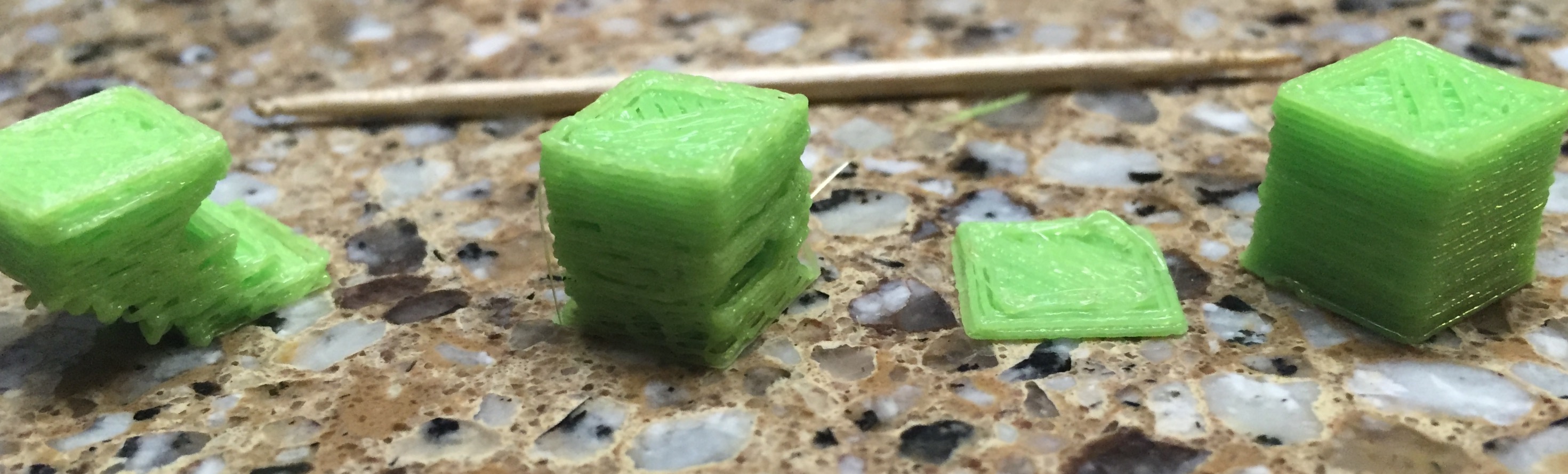
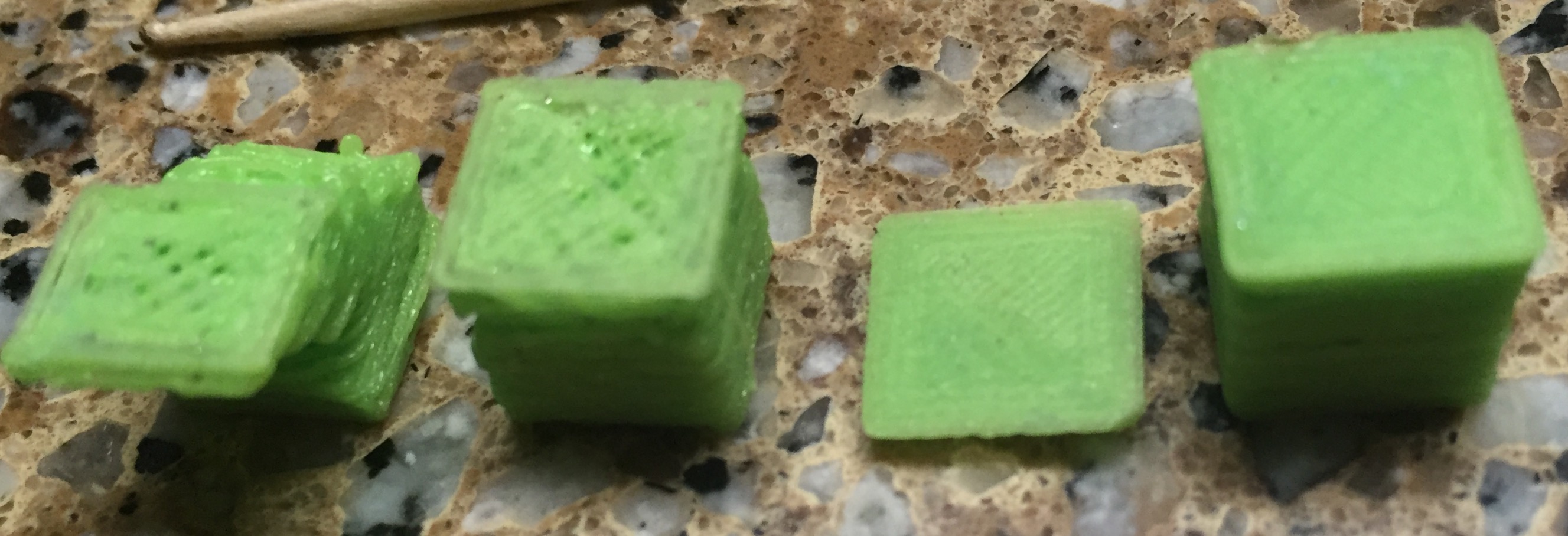
Ok, so I ran through this several times and settle on 96.8. I decided to try a 20 mm square cube and the attached photo is the result of the print. It's close to 20 mm square, if I can smooth out the print. First photo should be top and sides, second is bottom and sides.
That's absolutely horrible looking! Your print should look like this >
[attachment 64066 test_cube.jpg]
Hopefully, someone with more experience than I can pinpoint what's going on. To me, it looks like you've maladjusted something or many things in your slicer program. Or your layer thicknesses are 3.0 instead of 0.3? Or you have never adjusted your nozzle to bed clearance to 0.1mm?
When you were testing your extruder calibration, did you see large changes in how much it fed each time you tested the 100 mm? Maybe it's not feeding correctly or your voltage to the stepper motor is wrong. Clearly something is majorly wrong.
I'm starting to think I missed some steps somewhere. Anyway I played with it last night and attached it some photo of the result. left to right: slack in the belts, turn up with estep and adjust temp, printer clog, played wit estep and temp again. Now I got the firmware from from github so is there anything special I show be aware of with it? Reason being is I had to turn up the estep to 165 to get the last cube in the photos.
Edited 1 time(s). Last edit at 10/16/2015 04:33AM by Mopar99.
|
Re: Folger Tech 2020 i3 Printer Kit (Official Thread) October 15, 2015 05:51PM |
Registered: 8 years ago Posts: 99 |
Quote
Mopar99
Quote
tjnamtiw
Quote
Mopar99
Ok, so I ran through this several times and settle on 96.8. I decided to try a 20 mm square cube and the attached photo is the result of the print. It's close to 20 mm square, if I can smooth out the print. First photo should be top and sides, second is bottom and sides.
That's absolutely horrible looking! Your print should look like this >
[attachment 64066 test_cube.jpg]
Hopefully, someone with more experience than I can pinpoint what's going on. To me, it looks like you've maladjusted something or many things in your slicer program. Or your layer thicknesses are 3.0 instead of 0.3? Or you have never adjusted your nozzle to bed clearance to 0.1mm?
When you were testing your extruder calibration, did you see large changes in how much it fed each time you tested the 100 mm? Maybe it's not feeding correctly or your voltage to the stepper motor is wrong. Clearly something is majorly wrong.
I'm starting to think I missed some steps somewhere. Anyway I played with it last night and attached it some photo of the result. left to right: slack in the belts, turn up with estep and adjust temp, printer clog, played wit estep and temp again. Now I got the firmware from from thingiverse so is there anything special I show be aware of with it? Reason being is I had to turn up the estep to 165 to get the last cube in the photos.
I'm going to jump in and say "slow down" . Take one step at a time. The first thing I would do if I were you would be to back up. How tight are your belts? Make sure the pulleys are tight on the stepper motor shaft or it will skip and you will lose steps. Then after you think that is ok, take a digital caliper and check your axis's. And recheck them. Make changes in your firmware like you did on the extruder. Get them as close as possible. Then try a simple 20x20 cube.
|
Re: Folger Tech 2020 i3 Printer Kit (Official Thread) October 15, 2015 06:21PM |
Registered: 8 years ago Posts: 541 |
Quote
therippa
Quote
tjnamtiw
Quote
therippa
Quote
msaeger
Quote
therippa
For those waiting to pull the trigger on upgrading to lead screws, Banggood has them on sale right now for just $8.56 - [www.banggood.com]
What do you use for a coupling to the stepper motor with these?
[folgertech.com]
Yep, why go anywhere else? You won't find that any cheaper plus you're supporting a great US company that's treated us very well. No, I don't work for them! They just gave me great service when I most needed it.
Can't tell if you're trolling or not, but Leap3d also sells them, and I've had great experiences with them - [www.ebay.com]-
If you look at my brief time here, you'll see that I've tried to contribute to those who have had similar problems to those I've managed to solve. I'm far from a troll and I really resent that statement. I just so happen to have a Folger Tech 2020 that I've been running about 14 hours a day for weeks with zero problems. They also, as I stated, were very quick to respond to my early problems with missing parts due to the @#$% USPS. This is a Folger Tech thread so why not plug them and support them?
|
Re: Folger Tech 2020 i3 Printer Kit (Official Thread) October 15, 2015 07:12PM |
Registered: 8 years ago Posts: 276 |
Quote
tjnamtiw
Quote
therippa
Quote
tjnamtiw
Quote
therippa
Quote
msaeger
Quote
therippa
For those waiting to pull the trigger on upgrading to lead screws, Banggood has them on sale right now for just $8.56 - [www.banggood.com]
What do you use for a coupling to the stepper motor with these?
[folgertech.com]
Yep, why go anywhere else? You won't find that any cheaper plus you're supporting a great US company that's treated us very well. No, I don't work for them! They just gave me great service when I most needed it.
Can't tell if you're trolling or not, but Leap3d also sells them, and I've had great experiences with them - [www.ebay.com]-
If you look at my brief time here, you'll see that I've tried to contribute to those who have had similar problems to those I've managed to solve. I'm far from a troll and I really resent that statement. I just so happen to have a Folger Tech 2020 that I've been running about 14 hours a day for weeks with zero problems. They also, as I stated, were very quick to respond to my early problems with missing parts due to the @#$% USPS. This is a Folger Tech thread so why not plug them and support them?
I didn't mean it in a bad way, it's hard to judge sarcasm on the net. I haven't had any problems with Folgertech, but others have... I just couldn't remember if you were one of them.
Need help? Visit the Folgertech Wikia Page
The latest Marlin firmware with Folgertech Prusa i3 settings merged in, get it here
And check out my designs on Thingiverse, and follow me if you like what you see!
|
Re: Folger Tech 2020 i3 Printer Kit (Official Thread) October 15, 2015 08:09PM |
Registered: 8 years ago Posts: 57 |
Hi kn4ud, rippa,
You guys mind sharing some slic3r tips on PETG? I see you mention lift.. did not try that, going to do it myself.
I am having stringy hell right now
Sonny I have auto-level in place now via servo.. love it.. let me know what I can do to help.
Don't even bother trying to get the 5v bus on the stock folger to power the servo as-is. You'll need to wire up a separate 5V power supply to the ramps board for it.
Edited 1 time(s). Last edit at 10/15/2015 08:10PM by srcga.
|
Re: Folger Tech 2020 i3 Printer Kit (Official Thread) October 15, 2015 08:17PM |
Registered: 8 years ago Posts: 430 |
Quote
therippa
Quote
msaeger
Quote
therippa
For those waiting to pull the trigger on upgrading to lead screws, Banggood has them on sale right now for just $8.56 - [www.banggood.com]
What do you use for a coupling to the stepper motor with these?
[folgertech.com]
Orders two lead screws, the couplings and some misc socket cap screws. My first order direct from Hong Kong wish me luck!
Newbie with Folgertech 2020 i3.


Sorry, only registered users may post in this forum.