Geeetech-Aluminum-Prusa-I3
Posted by Anonymous User
|
Re: Geeetech-Aluminum-Prusa-I3 January 29, 2016 01:07AM |
Registered: 8 years ago Posts: 34 |
Quote
MKSA
How can you make sure these sensors give you the required repeatability ? You need better than 0.1mm. These sensors are designed and used for a totally different purpose.
I already mentioned testing in my previous post:
"LJC18A3-B-Z / BX I will get one and do some testing on an Arduino board " That is how I will know.
As for these sensors, many people have been using them for just such a purpose for many years and have reported success.
If I wanted to be extra sure, I'd spend $2000 to $5000 and buy one of the more expensive printers. Instead I have chosen to buy this printer, build it and enhance it. My aim is not to just print plastic things but to learn and develop. As anyone who has bought any such DIY printer, the support and warranty is almost NIL. YOU ARE ON YOUR OWN.
No guarantees.
Currently I am using a piece of paper and if I can get any more accurate than that, consistently and automatically then that is the way I go. As it is current the bed leveling system is inaccurate, tedious and one I want to eliminate.
|
Anonymous User
Re: Geeetech-Aluminum-Prusa-I3 February 01, 2016 05:06AM |
Quote
bernbout
Quote
MKSA
How can you make sure these sensors give you the required repeatability ? You need better than 0.1mm. These sensors are designed and used for a totally different purpose.
I already mentioned testing in my previous post:
"LJC18A3-B-Z / BX I will get one and do some testing on an Arduino board " That is how I will know.
As for these sensors, many people have been using them for just such a purpose for many years and have reported success.
If I wanted to be extra sure, I'd spend $2000 to $5000 and buy one of the more expensive printers. Instead I have chosen to buy this printer, build it and enhance it. My aim is not to just print plastic things but to learn and develop. As anyone who has bought any such DIY printer, the support and warranty is almost NIL. YOU ARE ON YOUR OWN.
No guarantees.
Currently I am using a piece of paper and if I can get any more accurate than that, consistently and automatically then that is the way I go. As it is current the bed leveling system is inaccurate, tedious and one I want to eliminate.
From what I have read, the sensors used are L type not C. Do you have any specs about their repeatability in this type of use ?
Edited 1 time(s). Last edit at 02/01/2016 11:35AM by MKSA.
|
Anonymous User
Re: Geeetech-Aluminum-Prusa-I3 February 03, 2016 08:50AM |
Just got my Geeetech I3 Prussa.
Well packaged, no part broken and none seem to be missing. All rods and Al plates not obviously bent or damaged.
For Z, I was expecting T8 lead screws but it's only M8 regular stainless steel threaded cold rolled rod .
The "fit" of the bronze nut is unfit, even more play than regular M8 nuts and bolts. OK for the Z except for the potential "wobbling" but couldn't be used for any other axis.
The linear guides and rods have some minor "play" but it seem acceptable for this use. I hope the rods will not mar too quickly.
Let's say it should hold 0.1mm provided some tweaking.Good luck for the 1/20th and anyone speaking "micron" even by ten will make me laugh.
Tolerance in mechanic seems to have followed the same path as in human society
Overall, for the price, my impression is OK.
But the proof of the pudding is in the eating, so back to the kitchen to prepare it
|
Re: Geeetech-Aluminum-Prusa-I3 February 11, 2016 12:43AM |
Registered: 8 years ago Posts: 188 |
|
Anonymous User
Re: Geeetech-Aluminum-Prusa-I3 February 12, 2016 11:09AM |
Quote
lexering1988
News?
I assembled it making sure it was as straight as possible. Overall, my impression, considering the price is rather good although plenty of improvements possible.
All parts are straight and flat within 0.1mm. Rods are plain stainless steel, hardened steel would be better, much more expensive.
As it is not super rigid, I mounted it on a 4cm thick piece of kitchen table top (no granite surface plate in my house
). I will reinforce the vertical plate latter.I modified the way the belt attaches to the Y plate using a clamp similar to the X axis. Geeetech does it with a hole in the belt and screws !!! Nonsense !!!!
I replaced the M4 bolts used as axis for the idlers by 4mm rod. A bolt is NOT an proper axis ! Will also replace the pulleys by one with sprockets.
The M8 rods are standard threaded stainless steel rod, too much play in the couplers. Not supported at the top, noisy. Usable, but I will replace them by T8, 8mm lead and modify to have only one motor for Z axis. M8 provides a 1.25mm lead, non sense here !
Of course, M3 knobs underneath to adjust the bed. Can't believe they didn't provide that either.
Put an adjustable screw on the X axis to actuate the micro switch so the extruder stays above the bed. Why Geeetech didn't do it, I don't understand.
Had a lot a fun watching Geetech videos, they managed to assemble it without caliper, ruler, square, gauges.
At least, it's metal, a "plastic" prusa would be junk, a dead end.
I printed some small parts to learn how to use it as I am just a beginner in 3D printing.
I like the Delta concept but didn't start with one because a cartesian is easier to tweak.
|
Re: Geeetech-Aluminum-Prusa-I3 February 12, 2016 11:51PM |
Registered: 8 years ago Posts: 34 |
|
Anonymous User
Re: Geeetech-Aluminum-Prusa-I3 February 13, 2016 10:44AM |
Just loaded the picture of the X mod for the micro switch and how to attach the belt to the table.
Speaking of micro snitches, I see they are used to zero the machine. This is not proper but here but acceptable for X and Y axis.
For the Z axis, it's an other story, here we need repeatability better than 0.1mm. So I dismounted it to find out how to improve it. I found the worst mechanism ever for this purpose (OK as security switches but ? ).
See here: Micro switch.
I will replace it by leaf spring and contact made out of gold plated beryllium copper.
|
Re: Geeetech-Aluminum-Prusa-I3 February 14, 2016 02:59PM |
Registered: 8 years ago Posts: 1 |
I have just finished assembling my Geeetech all aluminum Pursa I3 yesterday and have not been able to print anything successfuly yet the extruder motor slips and coggs with a clunk clunk clunk when printing. To much filament back pressure and not enough torque. Very poor extruder design. The print head temp sensor 100K termister is mounted in the wrong place away from, and on the otherside of the heater block away from the extruder tip.
This causes the temperature to be read higher than it really is and thus the extruder tip temperature is about 20 degrees low which causes printing at too low a tempeature. I changed out the heater block to a E3D type and that fixed the extrude temperature but didn't solve the Clunk Stepper slipping (Cogging). Not enough torque.
Is there a possibility that the extruder speed or steps/mm calibration is wrong causing the cogging problem. Are others having this same problem? Any Comments or solutions.
The machine is a fair machine but has some real short commings. The heater and temp sensor needs to have a wire disconnect connector to allow disassembly of the print head without over stressing the wires and make servicing the print head easier.
By the way some have had probles with the power supply I think what is happing because the supply is sent with the 110/220 Selection switch set to the 220 VAC setting. The supply kind of works on 110VAC with the supply Voltage Switch set to 220VAC but doesn't output enough current and drops to 8 Volts when under load. When set properly set it works fine regulates at 12VDC at full Load.
I am just starting to learn how to use Repetier and Slic3r. I have used 3d CAD for Years. New to 3D printers. Can someone maybe help me get the printer to print. frustrated with the Extruder.
I see so many extruders with large gears and this tells me that direct drive extruders are probably not a good design.
I guess the question is, has this direct drive worked for anyone else???
I have also had jamming probles in the heater break tube. The PTFE in the tube was too short and the PLA expanded into the gap in the tube and caused a blockage. I replaced the PTFE with a slightly too long tube and compressed the PTFE against the Extrusion TIP. This fixed the jamming.
Does anyone know what the calibration value for the extruder is in steps/mm and the relational speeds between the X,Y.
I know this is complex but must have some general rules.
Edited 1 time(s). Last edit at 02/14/2016 03:05PM by AllgoodEnergy.
|
Re: Geeetech-Aluminum-Prusa-I3 February 14, 2016 04:31PM |
Registered: 8 years ago Posts: 15 |
The clunking is possibly your extruder stepper motor skipping steps. Do you get the clunking sound when running the extruder manually with the nozzle well above the bed? If so, this could be a clogged nozzle, not enough current to the motor, or the temperature is too low.
If it occurs during the first layer of a print, then it may be your bed is too close. In Slic3r I run a layer height of 0.2mm and a first layer height of 0.3mm (with a 0.3mm nozzle).
Here are a couple things to check for the issues you are seeing with your extruder:
1. Do you have the correct nozzle diameter set in Repetier and Slic3r? You want to make sure it is set to the diameter of your nozzle (i.e. 0.3mm). In Repetier, go to Printer Settings -> Extruder tab and set the diameter as appropriate. In the Slic3r settings, go to Printer Settings -> Extruder 1 and set Nozzle diameter.
2. Increase the current to the stepper motor driver. I had to slightly increase the current when I first set mine up. If you do this with a metal screwdriver, be VERY careful not to short any other connections. It is best to use a ceramic or plastic screwdriver.
My extruder is completely stock and has worked fine except when something got clogged in the nozzle. I ended up removing the nozzle from the printer and heating it to a really high temperature with a heat gun which seemed to vaporize whatever was clogging the nozzle. It is working fine again although I will be ordering some spares to have as a backup.
For calibration, this is a good article on the processes: Quick Guide to Calibrating the Scale of Your 3D Printer.
Essentially what you want to do is print a test cube with known dimensions (like this 20x20mm cube. Next, measure the X and Y sides so you can recalculate the values for the Marlin configuration. You then update your DEFAULT_AXIS_STEPS_PER_UNIT value in Configuration.h in Marlin and re-upload that to the Sanguinolulu.
For example, lets say your X size measure 20.5mm and your X configuration value is 78.74. You calculate the new value like this: (20 / 20.5) x 78.74 = 76.8195
When I did this, I ended up with these values:
#define DEFAULT_AXIS_STEPS_PER_UNIT {80.63492062, 80.63492062, 2560, 95}
Note that I did not change my Z axis nor extruder values from what was stock.
|
Re: Geeetech-Aluminum-Prusa-I3 February 14, 2016 11:13PM |
Registered: 8 years ago Posts: 34 |
Quote
AllgoodEnergy
I have just finished assembling my Geeetech all aluminum Pursa I3 yesterday and have not been able to print anything successfuly yet the extruder motor slips and coggs with a clunk clunk clunk when printing.
By the way some have had probles with the power supply I think what is happing because the supply is sent with the 110/220 Selection switch set to the 220 VAC setting. The supply kind of works on 110VAC with the supply Voltage Switch set to 220VAC but doesn't output enough current and drops to 8 Volts when under load. When set properly set it works fine regulates at 12VDC at full Load.
That clunking sound is the stepper motor cogs slipping on your filament. Contrary to normal behaviour, you should LOOSEN the adjustment screw on top of the extruder to make the cogs grip better. I made the same mistake till I opened up the extruder and found my mistake. So if the cogs are slipping, LOOSEN the screw. Mine is almost fully loose for better grip. No more clink noise no more slipping.
Put some oil on all bearings and the threaded rods of Z or use silicone grease.
The problem with the 110/220 v is that in almost all countries in the world, they use 220 V AC. Only in the US do they still use 110 v and the old imperial system of measurement - inches, feet, furlongs and miles. With 3D printing everything has to be in mm or metric.
So the manufacturers set the default to 220 v to cater to most of the world. Also this has the safety benefit that if they set it to 110 then is anyone other than the US user were to plug in without checking, they will not blow their PSU. For the US user it will just not work properly on a setting of 220v and they will then have to change the switch manually.
I have not had to make any setting changes to my firmware (as yet). The only change I made was as described earlier in this post. You can see the samples of what I printed as well. I am also a complete newbie.
The only other change has been that I drilled a hole directly below the provided hole in the rear center of the PCB heated bed, into the Al plate below and now use 3 screws for leveling - 2 in front and one rear. Much easier and recommended.
So far I have been unsuccessful in printing ABS with much curling despite heat settings. I still have a few more things to try though - ABS juice, rafts etc. PLA is no problem.
Bed leveling has been my bugbear and still is.
|
Anonymous User
Re: Geeetech-Aluminum-Prusa-I3 February 15, 2016 03:28AM |
Be careful and never use silicone grease sold for faucet O rings. Use good quality (MoS or lithium based) grease and just for the lead screws. Grease collect dirt and grit. For linear guides, sewing machine oil or lubricant like BreakFree works well.
I am totally new to these 3D printers too but I found the Geeetech, considering its price to be acceptable and usable although plenty of improvements could be done and better quality parts used.
And it is metal, not an assembly of crappy acrylic plates.
It is easy to mount the print head in such a way it can be removed without difficulties. The print head wires can go through the big hole. I even replaced the M4 screws by M4 rod and wing nuts.
|
Re: Geeetech-Aluminum-Prusa-I3 February 15, 2016 06:13AM |
Registered: 9 years ago Posts: 762 |
Quote
MKSA
Had a lot a fun watching Geetech videos, they managed to assemble it without caliper, ruler, square, gauges.
At least, it's metal, a "plastic" prusa would be junk, a dead end.
Sory but I do not agree... I've got my GEEETech i3B, the acrylic one, more or less one yera ago..
... I have mounted without caliper/rule/square/gauge because I do not have them, and at this time the provider have not yet produce the video!
After that Ive' changed the M8 with T8 without any issue, and now my printer print very, very, very well...
Qualcosetta più che un neofina oramai, anche se non si finisce mai d'imparare!
DUE Stampati GEEETech i3B, GT2560+, Marlin GEEETech originale con un paio di modifichine personali (Pin dedicato per la Z Probe e stampa dell'ETE da SD), Barre Trapezie, Estrusore da 0.3 con filo da 1.75, una con estrusore metallico ed una con estrusore ridisegnato e stampato da me, Software AutoCAD/Slic3r/Repetier
My Thingiverse
My Linkedin
|
Re: Geeetech-Aluminum-Prusa-I3 February 16, 2016 10:55PM |
Registered: 8 years ago Posts: 34 |
Guys
Found this auto bed leveling system using the basic endstop.
[www.thingiverse.com]
Any comments would be appreciated, especially if they have relevance to the Aluminium Geeetech.
Found this auto bed leveling system using the basic endstop.
[www.thingiverse.com]
Any comments would be appreciated, especially if they have relevance to the Aluminium Geeetech.
|
Anonymous User
Re: Geeetech-Aluminum-Prusa-I3 February 17, 2016 01:07PM |
I noticed the printer is noisy due to vibration of the glass bed. Definitely the polished rods have too much play. Indeed I miked them at 7.94 mm. On the other hand, the linear guides seem OK as a polished pin measuring 8.005 slides perfectly but can't turn.
This is mainly for the Y axis. The X is fine, most probably because the bearings are under tension which acts as a preload.
Did any of you Geetech owner replaced these rods by cemented steel ones ?
I didn' like the way the thermister is installed, so just drilled a hole at an angle close to the extruder nozzle. I measured the T° of the said nozzle and now it matches the value displayed.
Overall, so far so good, no major flaw or irremediable design errors.
|
Anonymous User
Re: Geeetech-Aluminum-Prusa-I3 February 24, 2016 12:21PM |
As the Z zero is a key factor to have the bed at the proper initial height, I modified the Z microswitch as per the picture attached (no need for fancy detectors of unspecified repeatability and I consider autobed leveling useless for a properly assembled cartesian machine of decent quality). Works quite well as it goes OFF/ON for a 1/100th mm movement.
Not yet received the parts to modify for one stepper, synchronized lead screw Z axis.
Not yet received the parts to modify for one stepper, synchronized lead screw Z axis.
|
Anonymous User
Re: Geeetech-Aluminum-Prusa-I3 March 04, 2016 01:28PM |
Still waiting for some part from Banggood to get rid of one Z motor but just replaced the M8 rods by T8, 8mm lead. Just a bit more "professional", M8, it is to bolt things together, not move them
Quality is so so but then, it"s so cheap. Does the job. I doubt the nuts are bronze, just regular brass.
I built a new direct drive extruder to replace the MK8. I didn't like the hobbed gear, neither the idler assembly. I used polyurethane to build the idler, so no need for a spring, made a 8mm diam. soft steel hobbed gear and case hardened it. Won't see the end of it. I tested the grip and it holds 5daN. More than three time the factory gear. Weight 20g in PLA (temporary) and only 5 parts. not counting the motor and the hotend.
Put a lot a wingnuts to be able to service these quickly.
Would be nice to move the motor from the head but I don't like the Bowden approach. A transmission axle ?
I reused the hotend from the MK8. Not a very good hotend. A pain to dismount too. Gee who designs things like that ??? Will have to find something else. But one thing at a time.
Edited 1 time(s). Last edit at 03/04/2016 01:33PM by MKSA.
|
Re: Geeetech-Aluminum-Prusa-I3 March 06, 2016 02:47PM |
Registered: 8 years ago Posts: 34 |
|
Anonymous User
Re: Geeetech-Aluminum-Prusa-I3 March 06, 2016 10:39PM |
T8 rod and nut
Note: The fit is as sloppy as on a UNC bolt but it is still OK as the Z load, the X carriage weight, is one way and slow. For other use, a proper anti backlash nut must be devised. You get what you pay for.
At least banggood is honest, it doen't claim the nut is bronze while it is just brass.
Edited 1 time(s). Last edit at 03/06/2016 10:41PM by MKSA.
Note: The fit is as sloppy as on a UNC bolt
but it is still OK as the Z load, the X carriage weight, is one way and slow. For other use, a proper anti backlash nut must be devised. You get what you pay for.At least banggood is honest, it doen't claim the nut is bronze while it is just brass.
Edited 1 time(s). Last edit at 03/06/2016 10:41PM by MKSA.
|
Re: Geeetech-Aluminum-Prusa-I3 March 07, 2016 10:51AM |
Registered: 8 years ago Posts: 34 |
Looking at the rod from your link I see that the pitch of the threads is different - almost 7 mm looks like. Original threaded rod and firmware was for pitch of 1mm. How did you manage to get the correct Z movement? Did you modify the firmware and if so can you post some more details of what you changed?
I am also interested in doing this.
I have book marked 2 types:
1. long pitch - similar to yours
or T8-Lead-screw-T-type-stepper-motor-screw-T8X8-3D-engraving-machine-screw-300mm
and
2. with a 1mm pitch - http://www.aliexpress.com/item/3D-Printer-THSL-100-8D-Lead-Screw-Dia-8MM-Pitch-1mm-Lead-1mm-Length-100mm-with/32519052011.html
Wondering if #2 is actually a lead screw or same as what we already have. Any thoughts?
Edited 1 time(s). Last edit at 03/07/2016 11:09AM by bernbout.
|
Re: Geeetech-Aluminum-Prusa-I3 March 07, 2016 11:04AM |
Registered: 8 years ago Posts: 15 |
|
Re: Geeetech-Aluminum-Prusa-I3 March 07, 2016 11:22AM |
Registered: 8 years ago Posts: 34 |
I think he has to have made firmware changes as the pitch is close to 7.5 mm for 1 revolution of those rods, whereas stock firmware comes with the threaded rod of 1 mm pitch.
Also have a look at this method of Auto bed leveling using standard endstop switch and no servo. What do you think?
I was having huge probs with my bed being level as I had the printer on a foam sheet for noise reduction. On removing the sheet, and laying the printer on the bare table I saw that the main printer Y frame was skewed and not square. I straightened it out and after that - relief - I was able to level the bed in 3 minutes.
However one of the tiny bearings in the front - where the Y axis belt runs, just collapsed and split apart causing the Y Axis to seize and spoil my print after 2 hours.. Such cheap shoddy workmanship. So I have ordered new bearings and have to wait for them to arrive.
Things I intend doing:
Auto Bed leveling
Change the Z rods
Add Z backlash springs
LED Lights
later...
Edited 1 time(s). Last edit at 03/07/2016 11:37AM by bernbout.
|
Anonymous User
Re: Geeetech-Aluminum-Prusa-I3 March 08, 2016 02:49AM |
No wobble with the M8 or T8, I made sure to assemble and mount my printer properly and straight. It is an Al, by the way, no cut acrylic which is a joke.
The M8 is 1.25mm, the T8 I bought are 8mm lead (pitch 2mm, 4 start). 7.5mm lead doesn't exist. Refer to ISO specs for standard regarding screx, lead screw ....
M8 with 1mm pitch is a standard, it is M8 fine.Not designed as a lead screw. Cheap printer use the thinner M6 which pitch is 1mm as standard.
T8 with a 1mm pitch, are mainly used in CNC, small lathe or similar machines. I don't see any use on a Z axis, no real need for such a fine pitch.
No problem to change the Z it is done in the EEPROM. Just stay with metric, don't use ACME with inch pitch ! Gives rounding errors. AN age old problem but going away as not that many use "inch" anymore.
For me, no autobed leveling on a well assembled cartesian machine, a waste of time, adds weight and because the Z will have to go up and down, possible backlash and motor heat problem.
The link you showed made me laugh. So much complication !
OK for a Rostock system and most polar machine. Besides it is done with switch designed for.
No real need for an anti backlash nut on the Z as it goes one way and against the weight of the X axis. Could helps in case of vibration ? To be seen.
I ordered better quality (according to the "chinese" specs) rods claimed to be g6 class to repace the one of the Y axis. We will see if true. If OK, I may replace all the others too.
Chinese bearings are not high grade but bearings must be installed properly and carefully. You don't hit with a hammer to put them in place and always push on the outside rim. Too much force may mar the track and lead to failure. Furthermore, these bearing are very small and not designed for heavy load.
Edited 5 time(s). Last edit at 03/08/2016 08:32AM by MKSA.
The M8 is 1.25mm, the T8 I bought are 8mm lead (pitch 2mm, 4 start). 7.5mm lead doesn't exist. Refer to ISO specs for standard regarding screx, lead screw ....
M8 with 1mm pitch is a standard, it is M8 fine.Not designed as a lead screw. Cheap printer use the thinner M6 which pitch is 1mm as standard.
T8 with a 1mm pitch, are mainly used in CNC, small lathe or similar machines. I don't see any use on a Z axis, no real need for such a fine pitch.
No problem to change the Z it is done in the EEPROM. Just stay with metric, don't use ACME with inch pitch ! Gives rounding errors. AN age old problem but going away as not that many use "inch" anymore.
For me, no autobed leveling on a well assembled cartesian machine, a waste of time, adds weight and because the Z will have to go up and down, possible backlash and motor heat problem.
The link you showed made me laugh. So much complication !
OK for a Rostock system and most polar machine. Besides it is done with switch designed for.
No real need for an anti backlash nut on the Z as it goes one way and against the weight of the X axis. Could helps in case of vibration ? To be seen.
I ordered better quality (according to the "chinese" specs) rods claimed to be g6 class
to repace the one of the Y axis. We will see if true. If OK, I may replace all the others too.Chinese bearings are not high grade but bearings must be installed properly and carefully. You don't hit with a hammer to put them in place and always push on the outside rim. Too much force may mar the track and lead to failure. Furthermore, these bearing are very small and not designed for heavy load.
Edited 5 time(s). Last edit at 03/08/2016 08:32AM by MKSA.
|
Re: Geeetech-Aluminum-Prusa-I3 March 09, 2016 12:51PM |
Registered: 11 years ago Posts: 469 |
think you might need to take a long look at the physical properties of 6mm acrylic v alu Often the compression/tensile properties are better than alu, added to which ...thermal expansion . Just a thought when you come to strap your PSU to the frame :-)
I came across your thread when looking for more peoples opinion about ABL . One misconception that seems to be floating around is that ABL can compensate for a concave or convex bed . ABL simply measures the bed at specific points and forms a plane from the coordinates which it considers as being the bed. Only needs 3 points to determine this plane. any more test points simply average out the readings.
Im currently running a capacitative sensor and having spent a lot of time adjusting its sensitivity ( which many dont bother with) it produces very reliable results on a glass bed. Of course i also made a point of setting the bed up mechanically properly first.
As for the 8 mm lead screw as apposed to the Prusa i3 standard M5 i think its operates more smoothly. Its also theoretically faster as the steppers have to produce less motion to achieve the same Z height increase. The lead screw nut is also longer which reduces any potential backlash. I did try a temporary backlash system on them but didn't see any improvements at all in print quality so left them out.
Heres my X ends to suit the lead screw 8mm lead screw x ends
and made some adapters for the M5 die hards M5 anti back lash adapters
One thing i would definitely recommend you putting on your list of upgrades are the TMC silent stepper drivers for the x & Y axis . Without doubt the best bang for buck upgrade i have ever done to my printers.
good luck
Edited 1 time(s). Last edit at 03/09/2016 12:54PM by bigfilsing.
|
Anonymous User
Re: Geeetech-Aluminum-Prusa-I3 March 09, 2016 02:23PM |
Quote
bigfilsing
think you might need to take a long look at the physical properties of 6mm acrylic v alu Often the compression/tensile properties are better than alu, added to which ...thermal expansion . Just a thought when you come to strap your PSU to the frame :-)
I came across your thread when looking for more peoples opinion about ABL . One misconception that seems to be floating around is that ABL can compensate for a concave or convex bed . ABL simply measures the bed at specific points and forms a plane from the coordinates which it considers as being the bed. Only needs 3 points to determine this plane. any more test points simply average out the readings.
Im currently running a capacitative sensor and having spent a lot of time adjusting its sensitivity ( which many dont bother with) it produces very reliable results on a glass bed. Of course i also made a point of setting the bed up mechanically properly first.
As for the 8 mm lead screw as apposed to the Prusa i3 standard M5 i think its operates more smoothly. Its also theoretically faster as the steppers have to produce less motion to achieve the same Z height increase. The lead screw nut is also longer which reduces any potential backlash. I did try a temporary backlash system on them but didn't see any improvements at all in print quality so left them out.
Heres my X ends to suit the lead screw 8mm lead screw x ends
and made some adapters for the M5 die hards M5 anti back lash adapters
One thing i would definitely recommend you putting on your list of upgrades are the TMC silent stepper drivers for the x & Y axis . Without doubt the best bang for buck upgrade i have ever done to my printers.
good luck
Sorry but I maintain, no acrylic for me. No car, plane, machine tool made out of acrylic
I understand the concept of ABL and it is why I said it is useless for my machine. You said you spent a lot of time adjusting it. How about drift over time, t° .... Mfgs don't specify the repeatabilty of these sensors and when they do, it is a couple of percent of the detection distance. Also it is for exactly the same approach and target. Real positioning sensors are expensive.
The M5 are used because they are cheaper and the 0.8mm pitch gives impressive "accuracy" in fact resolution, a selling point to beginners.
The M series are to assemble things, not move things !
It is why I replaced the M8 by T8 8mm lead. No need for a finer pitch.
As I explained too, no need for a backlash nut.
Backlash doesn't depend on the nut length ! Of course, a longer nut, misaligned will give less backlash, but it is not the proper way to design.
One remark, the one under spring tension will be "springy" and if the spring is too strong will increase the required torque with M screws whose surface finish is not very good.
For the time being, I am modifying the Z of my Prusa for one stepper and belt to synchronize the lead screws. I just managed to splice a piece of GT2 belt to make a closed one. Doesn't break at 10 daN. Didn't try more.
I will get rid of the elastic coupler too.
|
Re: Geeetech-Aluminum-Prusa-I3 March 09, 2016 10:34PM |
Registered: 11 years ago Posts: 469 |
Spliced a GT2 belt !!! I bet that was fun . Im not sure there are any advantages to a single Z stepper other than machine weight and power consumption The original prusa's had a single stepper/ belt drive but over the years the dual stepper configuration has been adopted. I kind of get where you are coming from in modifying yours to a single but have to admit ive never had an issue with a dual set up. Of course having the same type/ brand of steppers and a good stepper driver is needed to maintain reliable sync'd operation. Wiring them in series isnt a bad idea either steppers in series
I think you need to view acrylic in the broader sense of thermo plastics then think of how much it is used in planes and cars. It isnt perfect in the application of our 3D printers ( but then again what is) but it brings an affordable, repeatable mass production accuracy to printer frames that allows non technical peoples to assemble a 3D printer that fits their budget.
The accuracy of Z sensors is more than adequate as it only effects the first layer of each print and as long as we get reasonable adhesion on the first layer were happy. It would be a different story if it was needed throughout the print process. Heated beds also don't help the repeat-ability as they never quite heat up the same every time hence non ABL set up needs to be done when everything is up to temp. Quite a few slicers allow for first layer compensation ( flow/height/width/extrusion) as well which can be useful.
The need for anti backlash isn't only determined by the thread-type/ pitch of the lead screw. The jerk & acceleration settings of the stepper(s) makes a huge difference and this is one area where i think you may come back from your intended mod to a single stepper. A Z axis driven by the belt will never react the same as the one driven directly and considering the Z movement ( jerk>acceleration>motion travel>deceleration>stop)for each print layer takes place in a matter of milliseconds dual steppers is the preferred method.
|
Anonymous User
Re: Geeetech-Aluminum-Prusa-I3 March 10, 2016 03:20AM |
Quote
bigfilsing
Spliced a GT2 belt !!! I bet that was fun . Im not sure there are any advantages to a single Z stepper other than machine weight and power consumption The original prusa's had a single stepper/ belt drive but over the years the dual stepper configuration has been adopted. I kind of get where you are coming from in modifying yours to a single but have to admit ive never had an issue with a dual set up. Of course having the same type/ brand of steppers and a good stepper driver is needed to maintain reliable sync'd operation. Wiring them in series isnt a bad idea either
I think you need to view acrylic in the broader sense of thermo plastics then think of how much it is used in planes and cars. It isnt perfect in the application of our 3D printers ( but then again what is) but it brings an affordable, repeatable mass production accuracy to printer frames that allows non technical peoples to assemble a 3D printer that fits their budget.
The accuracy of Z sensors is more than adequate as it only effects the first layer of each print and as long as we get reasonable adhesion on the first layer were happy. It would be a different story if it was needed throughout the print process. Heated beds also don't help the repeat-ability as they never quite heat up the same every time hence non ABL set up needs to be done when everything is up to temp. Quite a few slicers allow for first layer compensation ( flow/height/width/extrusion) as well which can be useful.
The need for anti backlash isn't only determined by the thread-type/ pitch of the lead screw. The jerk & acceleration settings of the stepper(s) makes a huge difference and this is one area where i think you may come back from your intended mod to a single stepper. A Z axis driven by the belt will never react the same as the one driven directly and considering the Z movement ( jerk>acceleration>motion travel>deceleration>stop)for each print layer takes place in a matter of milliseconds dual steppers is the preferred method.
The use of acrylic parts issue is manly in the way they are assembled. Aluminium or steel will always be better and why not composite but at what cost ? (cast iron and granite are better though
) are available for about the same price.I see plenty of people complaining out of synch Z steppers. To have them wired in // is a major error as it is the current that determine the torque. Furthermore, what about at power up ? I marked the position on mine and have seen that they were going out of synch ! Not much, a couple of steps.
I suspect it is just a matter of cost/simplicity that lead to the use of two stepperes.
Acceleration an issue for the Z axis ? I would like to see figures for this. On the X and Y, yes, but wait, belts are used !
Note that I am perfectly able to make a good antibacklash nut, done that in the past. I would prefer to use composite nut though. Just a matter a priorities and availability.
True, I haven't seen any satisfactory Z belt drive set up on the Prusa. I havn't been through all the thread though.To have the stepper attached to one of the lead screw via a flexible coupler and a belt from it to the other is not good. I have the two lead screws driven by the single Z motor. A bit like a double camshaft and crankshaft.
I set it up to be able to use an off the shelf belt of 760mm. Once I am satisfied, I will get one although my belt seems to hold after a few days. And I need it, to be able to print the new parts
ABL as I have seen it demonstrated with totally tilted bed, leads to constant correction in the Z but must also has be done for X and Y.
I bought a Prusa type just to get my hand on a cheap 3D printer. I do not consider it the best design, just does the job. I improve it as a game.
|
Re: Geeetech-Aluminum-Prusa-I3 March 10, 2016 04:24AM |
Registered: 11 years ago Posts: 469 |
i think you will be surprised at the quality and accuracy of printed parts if you are patient and spend some time on set up.
I've just come from a meeting with Igus where i have purchased some of their linear bush bearings. Hopefully they will be quieter than the standard LMU8's
they also have a whole range of supplies for 3D printers and what looks like some great filament. Looks like a good contender for a 3D printed anti back lash system.
how do you manage to see a couple of steps ??? 200 steps per rev X 16 micro steps = 3200 steps . If the differences are visible to the human eye then its more than " a couple of steps" and you should look at your system closely.
Torque is determined by both voltage and current. It is perfectly OK to have the z steppers wired in parallel tens of thousands of people have with no issues.
If i get a batch of steppers i always measure the Ohmns resistance of the coils and match up the motors closest to each other just in an attempt to "balance" things. I also make a point of making both Z stepper motors wiring looms the same length. Again trying to balance things out. Does it make a difference ?? Good question! But it certainly does no harm and my Prusa Air 2 hasn't missed a beat in over 3 years.
I would strongly recommend you consider going back to a dual Z motor set up. Regardless of what i think/say, everybody has gone down this route , even the ultra cheap Asian manufacturers who are always looking to simply machines to cut cost and give them the edge in the market. There must be a reason for this !!!
Good luck
|
Anonymous User
Re: Geeetech-Aluminum-Prusa-I3 March 10, 2016 07:40AM |
Quote
bigfilsing
i think you will be surprised at the quality and accuracy of printed parts if you are patient and spend some time on set up.
I've just come from a meeting with Igus where i have purchased some of their linear bush bearings. Hopefully they will be quieter than the standard LMU8's
they also have a whole range of supplies for 3D printers and what looks like some great filament. Looks like a good contender for a 3D printed anti back lash system.
how do you manage to see a couple of steps ??? 200 steps per rev X 16 micro steps = 3200 steps . If the differences are visible to the human eye then its more than " a couple of steps" and you should look at your system closely.
Torque is determined by both voltage and current. It is perfectly OK to have the z steppers wired in parallel tens of thousands of people have with no issues.
If i get a batch of steppers i always measure the Ohmns resistance of the coils and match up the motors closest to each other just in an attempt to "balance" things. I also make a point of making both Z stepper motors wiring looms the same length. Again trying to balance things out. Does it make a difference ?? Good question! But it certainly does no harm and my Prusa Air 2 hasn't missed a beat in over 3 years.
I would strongly recommend you consider going back to a dual Z motor set up. Regardless of what i think/say, everybody has gone down this route , even the ultra cheap Asian manufacturers who are always looking to simply machines to cut cost and give them the edge in the market. There must be a reason for this !!!
Good luck
I know about synthetic bushing and would not hesitate to use them, just that I have been playing with this Prusa for less than 3 weeks. They require ultra smooth rods which is not what Geetech supplied. They are not g6 class either and I have ordered some expecting they will be. The noise with ball bushing is also due to this.
Easy to see that a few step have been missed. At home Z, just put pen mark on the frame and for ex. the flexible coupler for both.
Its simpler for Chinese to provide two steppers, have them wired in //, provide smooth idler pulleys, non g6 class rods, standard M series screw instead of proper lead screw etc....
I never cared what "everybody" does if itsn't backed by strong evidences, numbers, formulae, facts ....
As for the motor, YES ! only the current, construction and magnetic field intensity (the internal magnet here) determine the torque, not the applied voltage. Refer to any engineering book. It is why you drive them with a current source and they have to be in series. In // you can't be sure they will get the same current, mainly because of different resistance and inductance. So sorting them out based only on resistance is not the absolute answer.
Edited 2 time(s). Last edit at 03/10/2016 07:41AM by MKSA.
|
Anonymous User
Re: Geeetech-Aluminum-Prusa-I3 March 12, 2016 04:57AM |
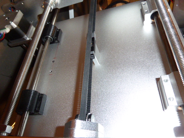
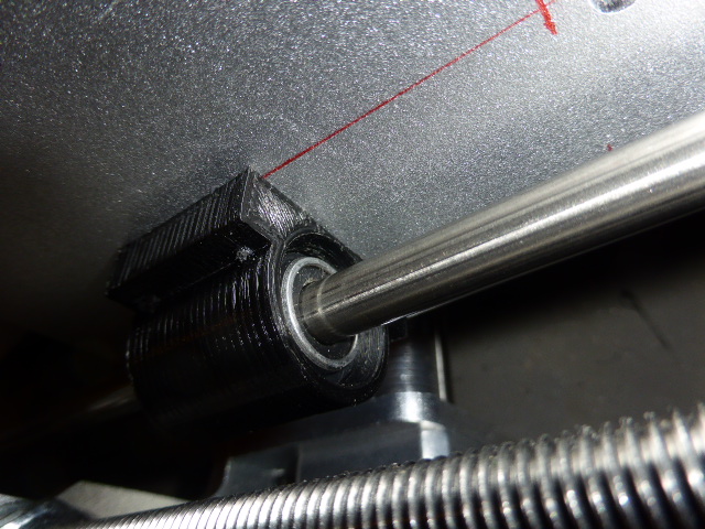
While waiting for decent guide rods, I designed a linear bearing housing in order to be able to preload them to take out excessive play and take care of small misalignment. The idea is to have the bearing fitted in the housing with two O rings. To do on one rod, the other being the reference axis so to speak. I used M3 instead of the M4 to be able to adjust their position. O rings are regular 12 X 2.6. One can try different sizes to adjust the system elasticity.
One can feel less play, less vibration in the bed, yet not perfect, the current guide rods being so out of spec. Can't preload too much for fear to mar them as they are soft stainless and lack stiffness (8mm only).
One can feel less play, less vibration in the bed, yet not perfect, the current guide rods being so out of spec. Can't preload too much for fear to mar them as they are soft stainless and lack stiffness (8mm only).
|
Anonymous User
Re: Geeetech-Aluminum-Prusa-I3 March 14, 2016 02:04PM |
NO MORE OUT OF SYNC Z motors for me  !
!
3 pulleys, two ball bearings replacing one stepper and two lame flexible couplers. Easier to adjust too, same procedure as for an engine timing belt , once done, OK for 150 000 km.
After a few days, the GT2 closed loop belt I made is still holding. Loctite Super Glue makes wonder. As I don't use any idler, no change in the way it bends, so less stress.
With the current pulleys, 20 t for the motor, 36 for the lead screws, I measured the torque required to be around 3.5 Ncm to move up. The belt splice although not perfect has no real effect. Can be felt when we turn by hand but minimal.
Nevertheless, I will order one, I designed the set up for a 760mm which is not uncommon.
!3 pulleys, two ball bearings replacing one stepper and two lame flexible couplers. Easier to adjust too, same procedure as for an engine timing belt
, once done, OK for 150 000 km.After a few days, the GT2 closed loop belt I made is still holding. Loctite Super Glue makes wonder. As I don't use any idler, no change in the way it bends, so less stress.
With the current pulleys, 20 t for the motor, 36 for the lead screws, I measured the torque required to be around 3.5 Ncm to move up. The belt splice although not perfect has no real effect. Can be felt when we turn by hand but minimal.
Nevertheless, I will order one, I designed the set up for a 760mm which is not uncommon.


Sorry, only registered users may post in this forum.