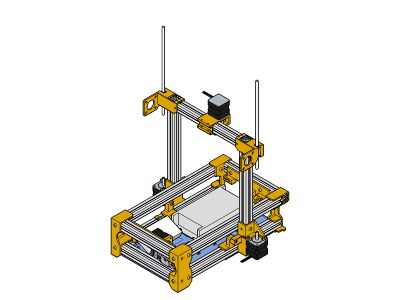
FoldaRap Build Manual
|
English • العربية • български • català • čeština • Deutsch • Ελληνικά • español • فارسی • français • hrvatski • magyar • italiano • română • 日本語 • 한국어 • lietuvių • Nederlands • norsk • polski • português • русский • Türkçe • українська • 中文(中国大陆) • 中文(台灣) • עברית • azərbaycanca • |

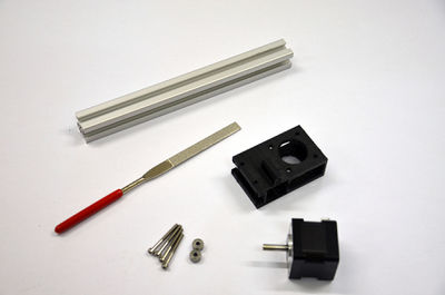
Tools required
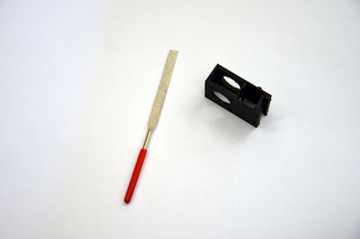
- 1,5 mm hexagonal wrench (for the pulleys grub screw)
- 2 mm hexagonal wrench (for M3 counterksunk bolts and pneumatic fittings "MA-12-03-M5")
- 2,5 mm hexagonal wrench (for normal M3 cap-head bolts and the rounded M4 bolts used for the frame)
- a flat screwdriver (for the psu's screw terminals)
- s small screwdriver (to set the drivers current)
You may need also :
- a 5,5mm flat spanner or a small pliers (for m3 nuts)
- something to cut wires, and strip them (knife, automatic striper, etc.)
- a lighter for the heat-shrink sleeves
- soldering iron (to eventually solder the endstops)
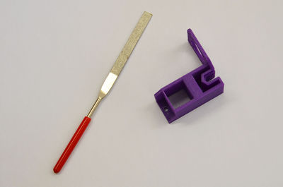
- small files (round, flat) to eventually ream the printed parts
Contents
- 1 Previous Version
- 2 General tips
- 3 Base Frame
- 4 Z-axis
- 5 Underplate
- 6 Z-sliders
- 7 X-axis
- 8 Z-rods
- 9 Extruder(s)
- 10 Top-frame (need update)
- 11 Great ! You are almost done !
- 12 Hotend
- 13 Bed-Plate
- 14 Electronic Board
- 15 Wiring
- 16 Tidying
- 17 Y-axis
- 18 Tape (5-10 min)
- 19 Making the bed parallel and zeroing
- 20 Software side
- 21 Go go go first print !!!
Previous Version
The build manual for the FoldaRap 1 is here, the FoldaRap 2 is here.
While this one will evolve to become the version 2.5 build manual soon.
General tips
- Read the whole manual once or twice before starting, to get an overview of the build
- Basically we have a main frame and several sub-assemblies, some can be done in parallel : gather your friends and establish a record for minimum building time ! (Actual best record : 4 hours)
- Work on a cutting mat if you have one, it will protect your table plus they often show a millimetre grid that will be useful to check the bolts length (with some experience you will recognize them just by looking or holding one).
- Place you mouse over a picture in a list if you wonder what part it is
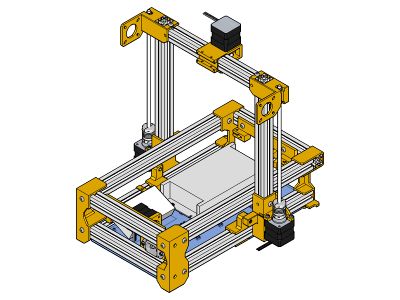
- In case of doubt, don't hesitate to have a look at the 3d model in Sketchup (before/during the build), even if about a next version of the machine it will show you the folded/unfolded state of the machine and you can play around with it :)
Ok let's start
It should take approximately 12 hours to put everything together.
From step 1 to 4 : 2-4 hours
Know the parts
Firstly, have a look at all the part and learn what everything is.
foot-front left
foot-front right
foot-rear left
foot-rear right
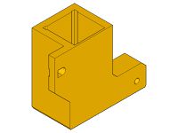
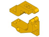
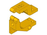
hinge-outer left
hinge-outer right
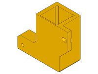
hinge-inner left
hinge-Inner right
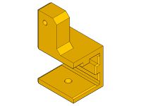
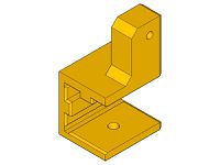
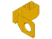
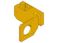
z-motor-bracket left
z-motor-bracket right
z-top left
z-top right
y-idler
y-carriage
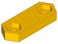
belt-clamp
y-motor
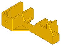
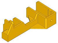
extruder left
z-slider left
z-slider right
extruder right
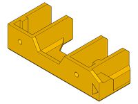
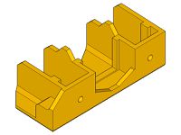
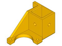
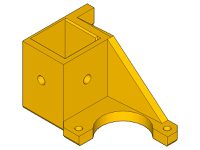
x-slider
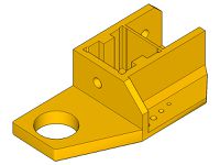
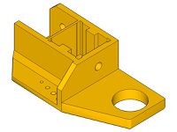
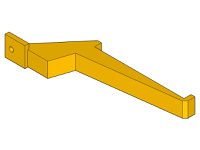
hotend-holder
fan holder
board mounts
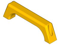
handle
spool-holder
underplate
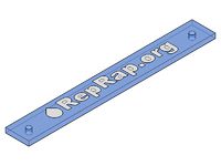
reprap.org plate


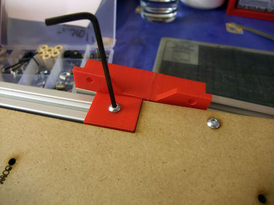
How to insert a T-nut
 Tightening torque : 2.5 Nm (+/- 5%)
<videoflash>9CAiVmfO2mk|320|240</videoflash>
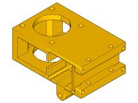
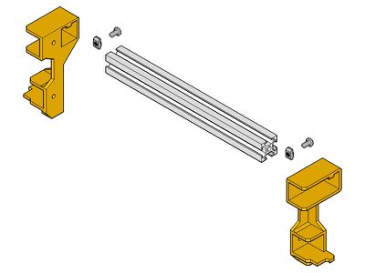
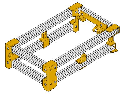
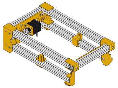
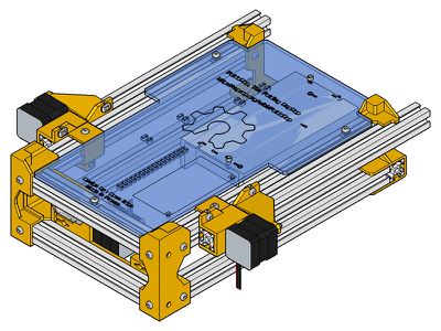
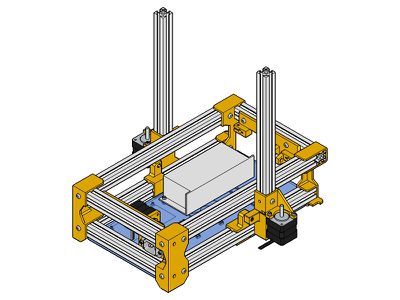
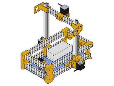
Base Frame
Rear Base
 x1 foot-rear-left
 x1 foot-rear-right
 x2 200mm profile
 x4 m4x8
 x4 t-nut
exploded view
tips : use the other extrusions to help you while adding the first two nuts
assembled


Front Base
 x1 foot-front-left
 x1 foot-front-right
x1 200mm profile
x2 m4x8
x2 t-nut
x1 foot-front-right
x1 200mm profile
x2 m4x8
x2 t-nut
exploded
tips: keep it flush by pushing the extrusion in from the flat side of the foot
assembled


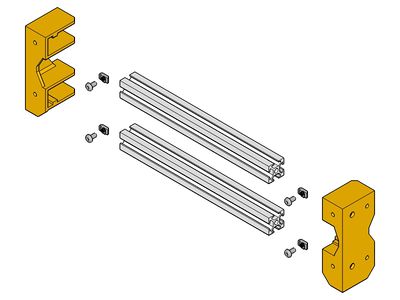
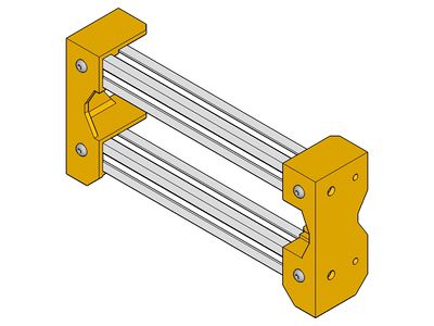
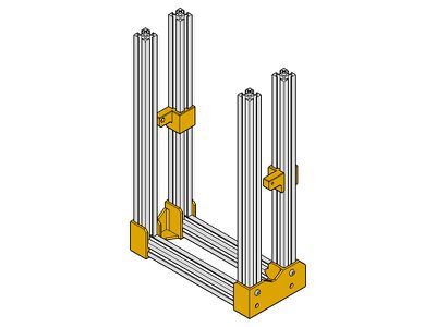
Base Frame
 x1 rear assembly
 x1 front assembly
 x1 hinge-inner-left
 x1 hinge-inner-right
 x4 300mm profile
x10 m4x8
x10 t-nut
x4 300mm profile
x10 m4x8
x10 t-nut
slide the hinge-inners on two 300mm extrusions, don't lock them yet


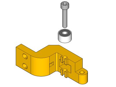
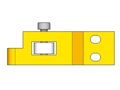
Y-idler
 y-idler
 x1 m3x20
 x2 603zz bearing
x2 m4x8
x2 t-nut
x2 603zz bearing
x2 m4x8
x2 t-nut
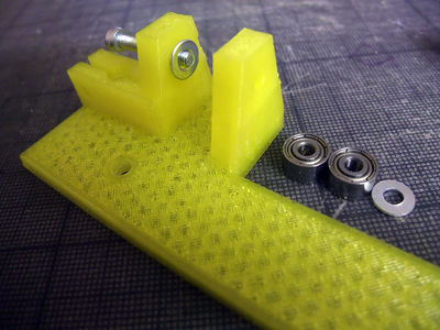
tips : it's easier to add everything while holding the y-idler in vertical position
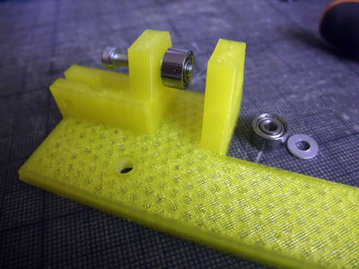
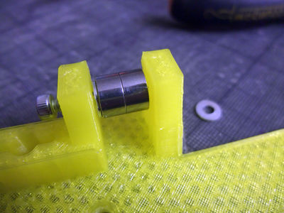
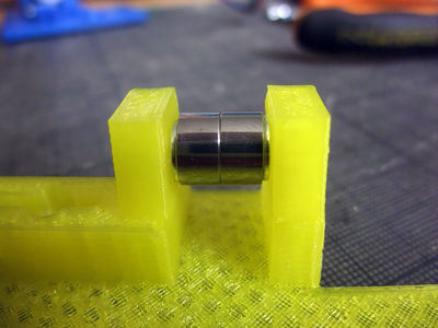
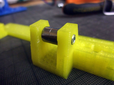
then add it on the frame, don't fully tighten the T-nut, you will need to move it slightly later to center it


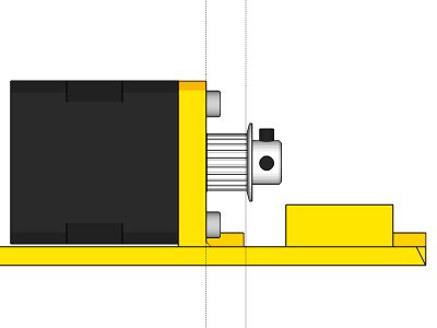
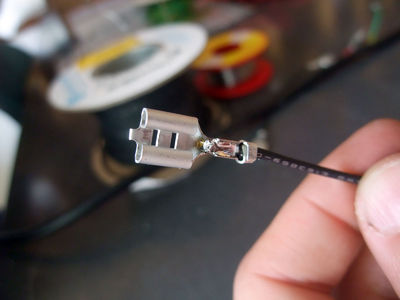
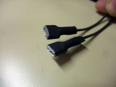
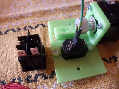
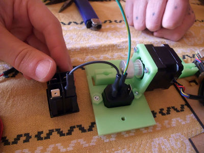
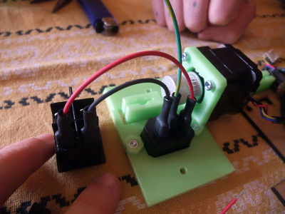
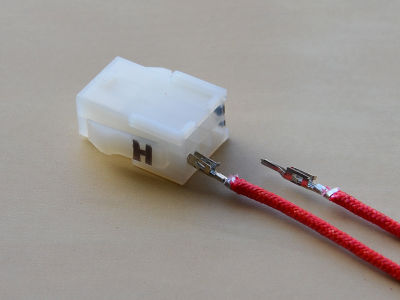
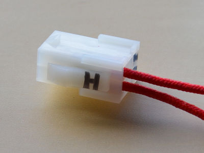
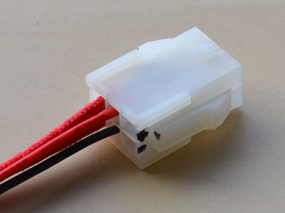
Y-motor
Plug
 x1 y-motor
 x1 plug
 x2 m3 nut
 x2 m3x8
add the male plug with 2 m3x8 and 2 m3 nut


Motor
x2 m3x8
 x1 nema 14 stepper motor
 x1 pulley
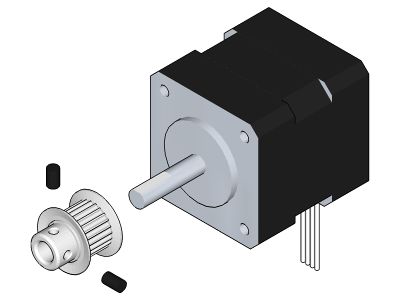
add the pulley on the motor shaft, and lock it with the grubscrew on the flat of the shaft
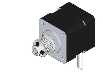
check that the flange is aligned along the plastic
add the motor with 2 or 3 m3x8, the wires pointing downward


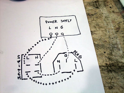
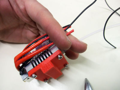
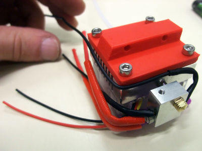
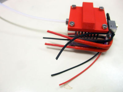
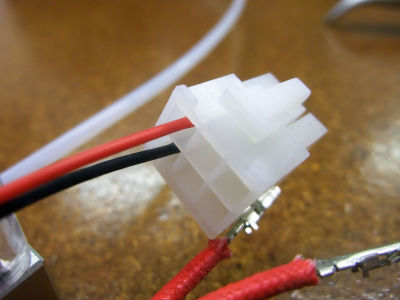
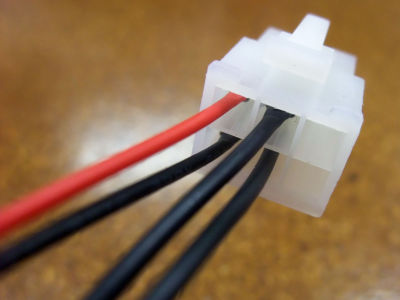
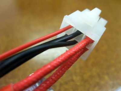
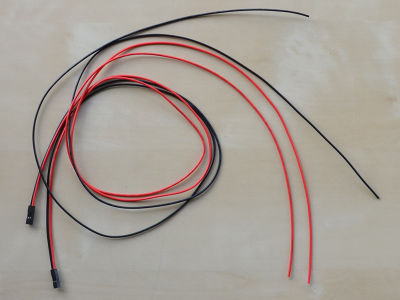
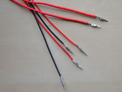
Wiring
 x7 ferules
 heat-shrink sleeve
 x1 switch
x3 m4x8
x3 t-nut
x1 switch
x3 m4x8
x3 t-nut
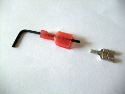
if you have insulated ferules, you can crimp them over plastic with a big pliers or push them out with a small hex key
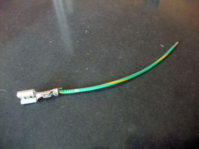
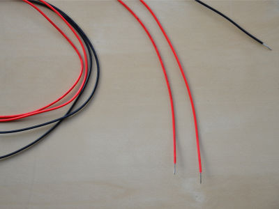
cut some wires : 1 green wire 18WG one end with ferule, the other end just stripped (male plug Ground to power supply Ground)
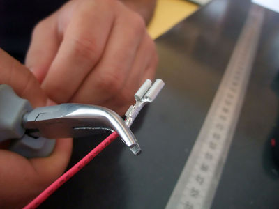
crimp the ferules on the wires
eventually add a drop of solder to make a perfect connection
don't forget to insulate the ferules with the heatshrink sleeve (or to put back the plastic case)
the green wire in place, now to the red/black ones !
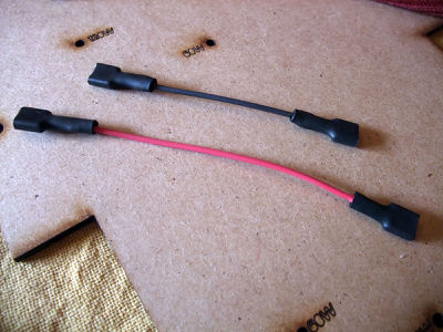
1 red wire of 9cm, 1 black of 7cm 18AWG, both ends with ferule (male plug Live/Neutral to switch Live/Neutral)
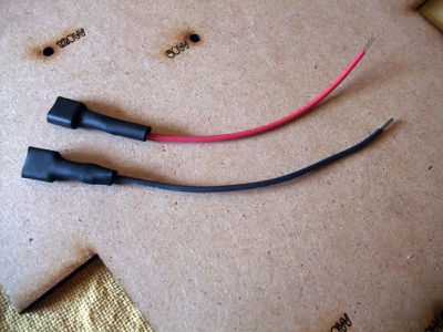
1 red and 1 black wire 18AWG one end with ferule, the other end just stripped (blue-switch Live/Neutral to power supply Live/Neutral). You may need longer wires depending of the power supply and it's position on the underplate, it may be good to shorten them later, once the psu is in place.
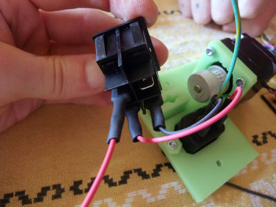
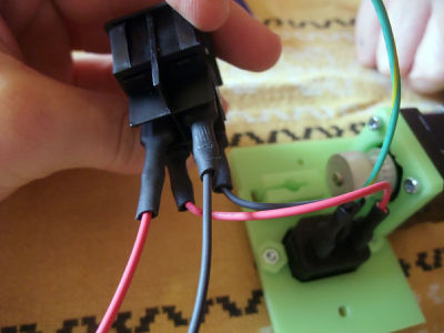
add the t-nuts
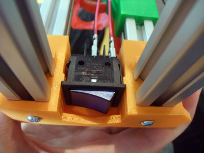
put the big blue switch in the rear-foot
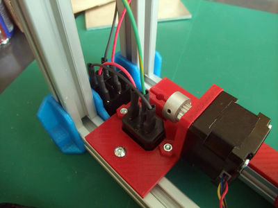
now you can lock the Y-motor while pushing it against the same rear foot (the two small bumps helps to center the Y-motor)
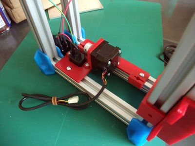
pay attention to really lock the t-nut near the plug, as it is easy for now and later you will push against it when you plug the power cable in


A part of the wiring depend of the combination of electronic board and power supply, for other version : FoldaRap_power-supplies
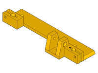
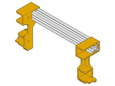
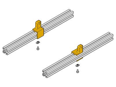
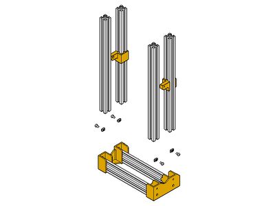
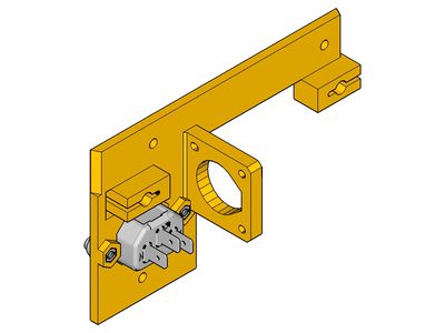
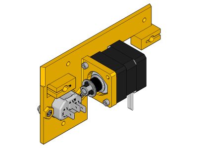
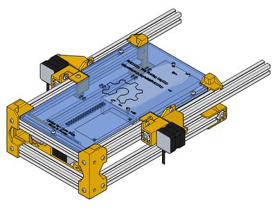
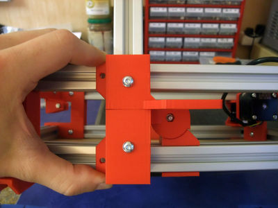
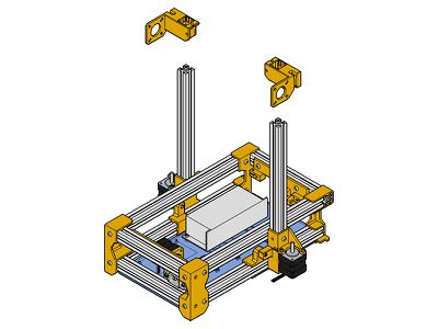
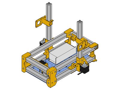
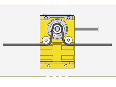
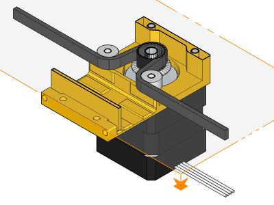
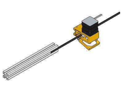
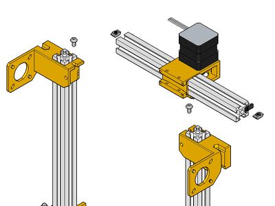
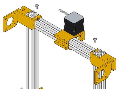
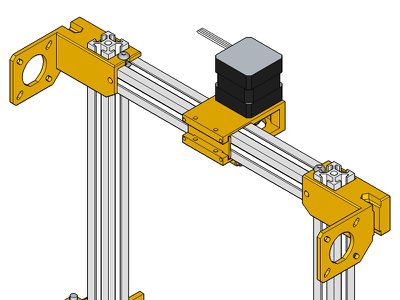
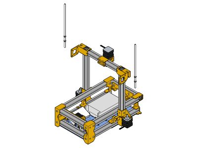
Z-axis
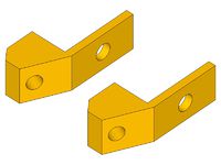
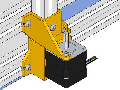
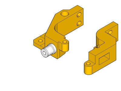
Z-Left / Z-Right
 x1 hinge-outer-left
 x1 hinge-outer-right
 x1 z-motor-left
 x1 z-motor-right
x2 300mm profile
x4 m4x8
x4 t-nut


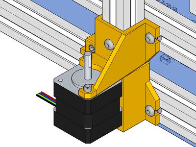
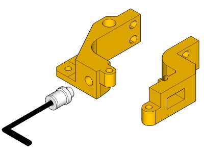
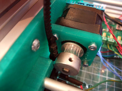
Z-Motors
x2 nema14
x4 m3x8


Hinges

 x2 m3x20
x2 m3 nut
x2 m3x20
x2 m3 nut


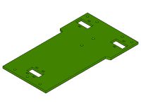
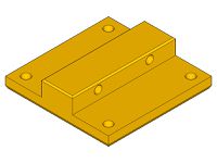
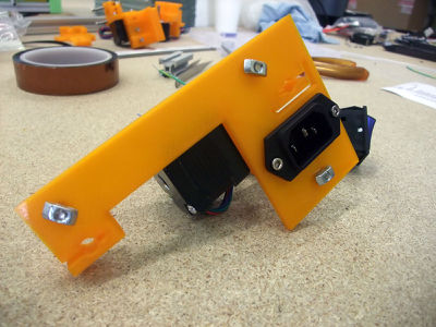
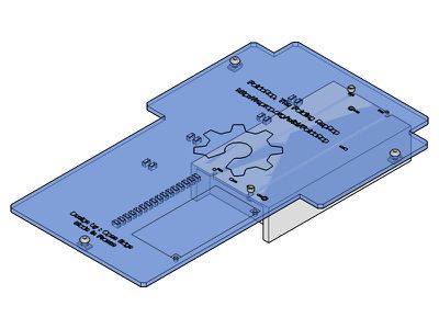
Underplate
Power Supply
Different kind of power supply have been used in FoldaRap builds, if you don't recognize yours look at this page : FoldaRap power-supplies
Anyway, the principle is always 1) bolt the power supply on the plate, 2) then the plate on the base of the frame
 x1 power supply
x2 m3x8
x2 m3 nut
x1 power supply
x2 m3x8
x2 m3 nut
 x1 lasercut underplate
x3 m4x8
x3 t-nut
x1 lasercut underplate
x3 m4x8
x3 t-nut
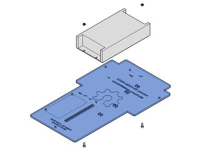
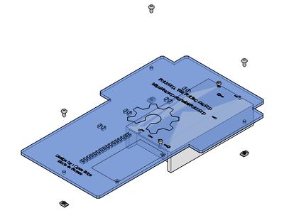
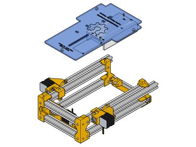
Now you can push the hinge against the plate
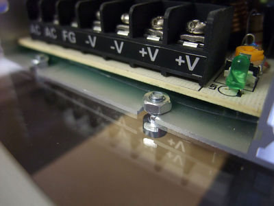
you can wire the plug to the power supply now or at a later stage, if the psu is not labelled the model is usually Live / Neutral / Ground


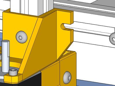
Z-axis position
x4 m4x8
x4 t-nut
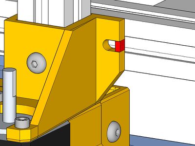
if you remove the support (red zone) the folding/unfolding of the XZ gantry will be easier/quicker


Z-sliders
 z-slider-left
 z-slider-right
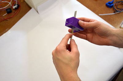
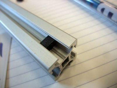
if needed, clean the inner faces of the z-sliders, until it fit on the profile, and slide well without play
impregnate the inner faces with oil for better sliding
it may be the occasion to add a m3x25 in the hole under the left slider, it will act later as a trigger for the Z endstop


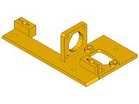
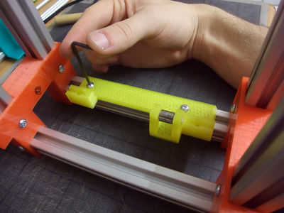
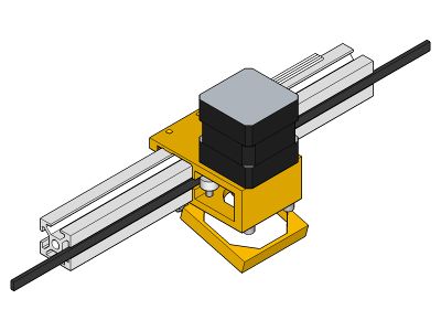
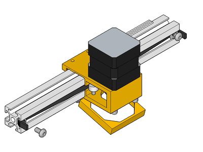
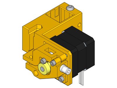
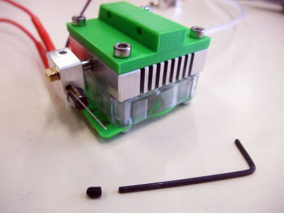
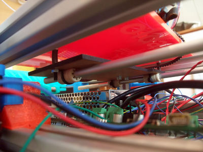
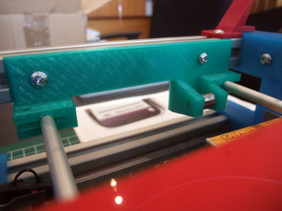
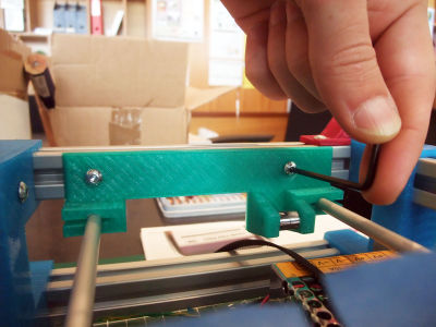
X-axis
X-slider
 x-slider
x1 nema14 stepper motor
x-slider
x1 nema14 stepper motor
 x1 pulley
 x4 M3x30 countersunk head
x2 603zz bearing
x4 M3x30 countersunk head
x2 603zz bearing
if needed, clean the inner faces of the x-slider
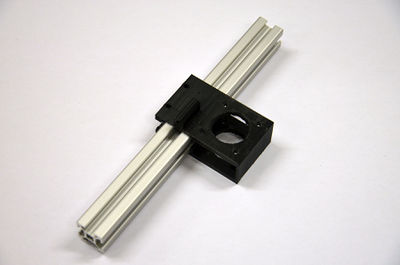
until it fit on the profile, and slide well without play
add the pulley on the motof shaft
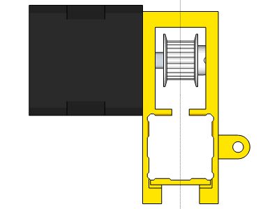
use the x-slider to position it at the center of the belt path
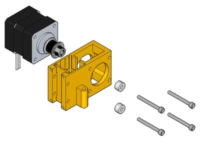
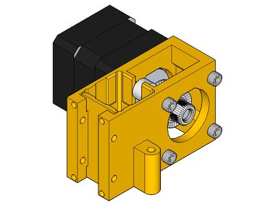
check if the slider slide well on the profile, impregnate the inner faces with oil for better sliding
(if the bearing is too loose, you can add one or two washers


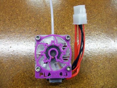
Fan-holder
 fan-holder
x1 m3x25
fan-holder
x1 m3x25


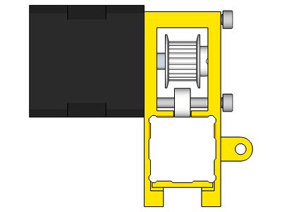
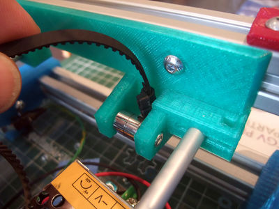
X-belt
x1 200mm profile
 x1 250mm belt
x2 m4x8
x2 t-nut
x1 250mm belt
x2 m4x8
x2 t-nut
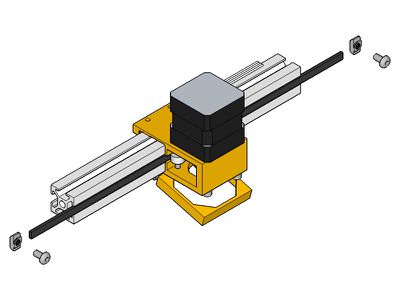
in addition, before the t-nut, add the small "belt-end" that will offset the belt along the profile (avoiding the uneven tension between the middle and the sides)

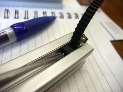

make sure to tighten well the belt when locking the second point


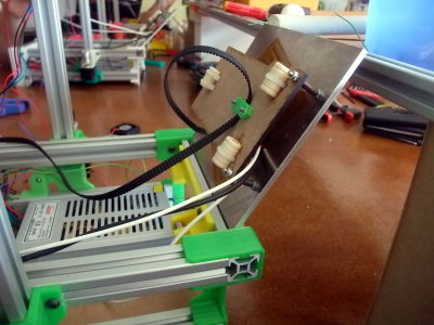
XZ-axis
x2 m4x8
x2 t-nut
check if the whole X-axis slide well along the vertical profiles


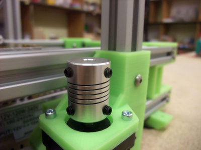
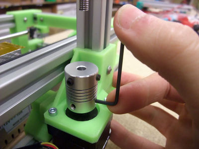
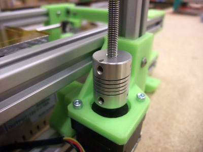
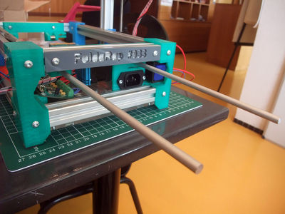
Z-rods
 x4 M5 nylon nut
 x2 M5 threaded rod 230mm
 x2 flexible coupling
<videoflash>iZKFV5miQEk|320|240</videoflash>
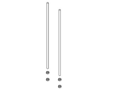
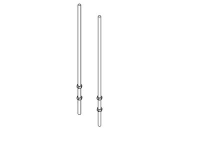
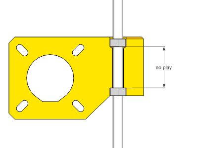
there should be no play between the nuts and the printed part, too much play will cause Z backlash, but the rod should turn easily, if the nuts are too tightened it constraint the movement of the rod (the open space allow the rod to eventually wobble without transferring it to the part, as you can see on this video [1])


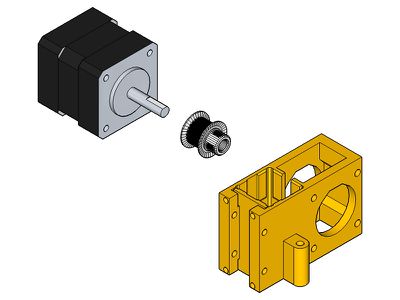
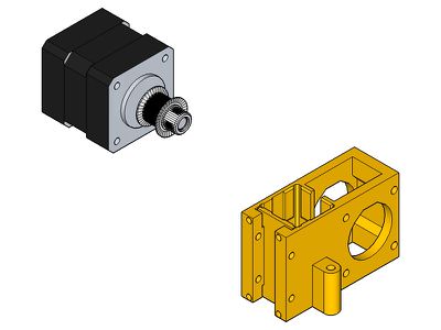
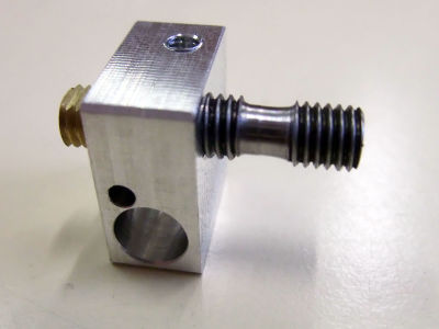
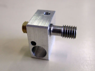
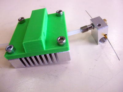
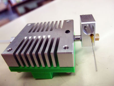
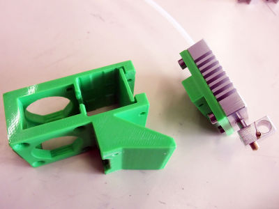
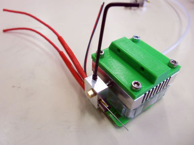
Extruder(s)
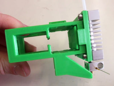
 extruder-left
  x1 pneumatic-fitting
 x1 m3x16
x1 603zz bearing
x1 m3x16
x1 603zz bearing
(and/or extruder-right  )
)

remove the support (in red)
if the entrance seems a little rough, you can make a small chamfer
screw the pneumatic fitting in the plastic with the 2mm hex key


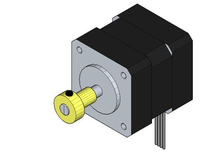
x1 nema14 stepper motor
 x1 knurled insert (juste one)
x2 m3x10
x1 m3x20
x1 knurled insert (juste one)
x2 m3x10
x1 m3x20
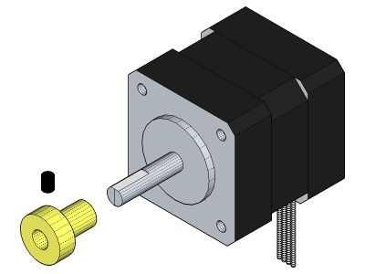
add the drive-gear on the motor shaft (make a flat if there isn't one)
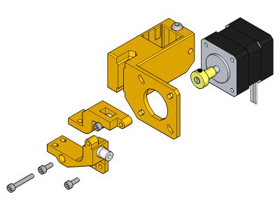
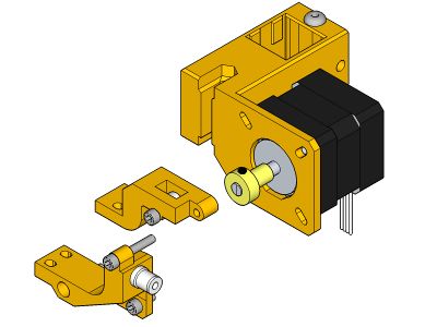


 x2 M3x35
 x2 spring
x2 M3 nut
x2 spring
x2 M3 nut


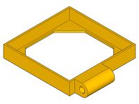
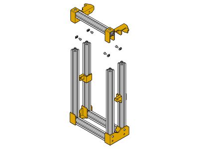
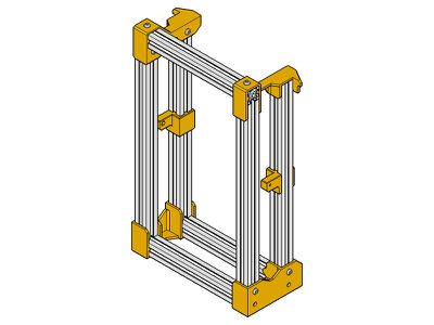
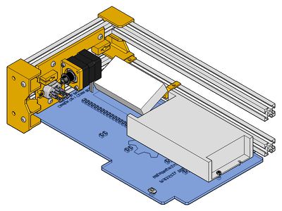
Top-frame (need update)
 x1
x1
 x1
x1
x4
x4
x1
x1
x4
x4
 x1
x2
x2
x1
x2
x2
 x1
x2
x2
x1
x2
x2


Great ! You are almost done !

Have a pause, you need to be relaxed for the next step, or you can also just head to the end :)
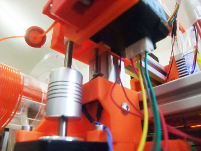
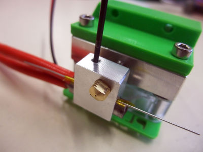
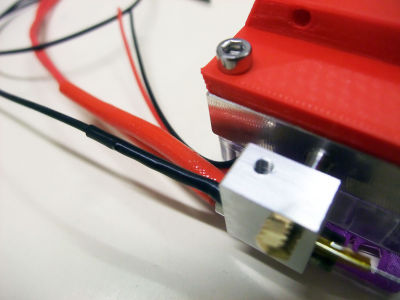
Hotend
Heater
 x1 heater block
 x1 nozzle
 x1 barrel
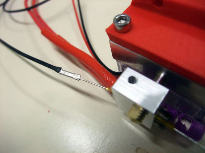
 x1 thermistor
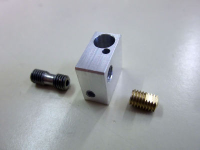
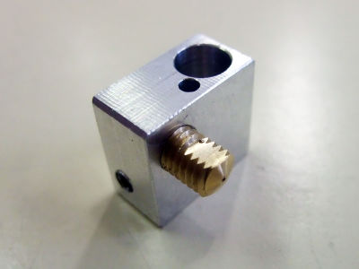
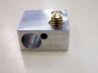
screw the nozzle into the heater block until the nozzle meplat get aligned with the flat part of the heater block
screw the barrel into the heater block until it touches the nozzle
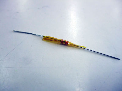
wrap the thermistor with a pice of Kapton...
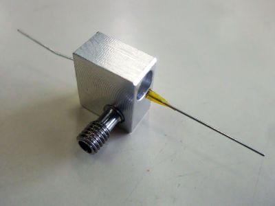
... and place it into the heater block


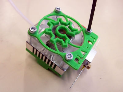
Heatsink
 x1 hotend heatsink (+ tube holder)
 x1 PTFE tube
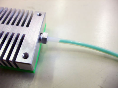
pass the PTFE tube in the tube holder and pass it through the heatsink hotend
screw the tube holder in the heatsink hotend


 x1 hotend holder
x4 m3x8
x1 hotend holder
x4 m3x8
orient the hotend heatsink so that the side with 5 holes is placed on the table (invisible)
screw the m3x8 into the hotend heatsink (on the side with 4 holes) through the hotend holder
push the PTFE tube in the barrel as much as possible
screw the barrel in the hotend heatsink...
... until the thread is aligned with the bottom part of the hotend heatsink and the edges of both metal parts are parallel (the longer part of the heater block is oriented towards the front of the hotend)
check the alignment of the heater block with the spout of the x-slider
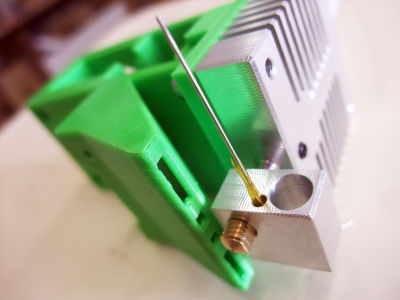
the bottom part of the heater block must be aligned with the upper part of the spout holes
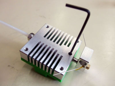
if the alignment is ok then fix the barrel in the hotend heatsink with a grubscrew
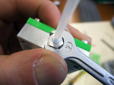
tighten the tube holder on the PTFE tube with a spanner: tight enough so that the tube is hold...
... but not too much so that the filament can still pass through it


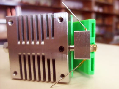
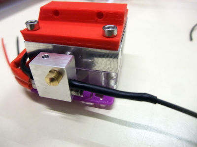
Fan
 x1 fan
 x1 fan railings
x4 m3x16
x1 fan railings
x4 m3x16
 x4 m3 washer
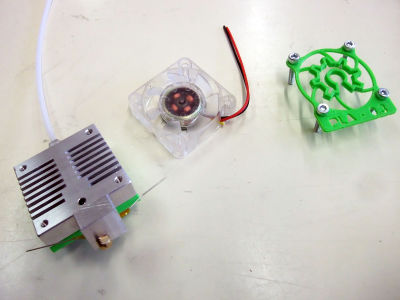
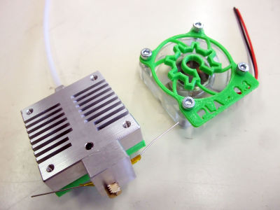
pass the 4 screws through the fan railings and the fan (wires oriented downward)
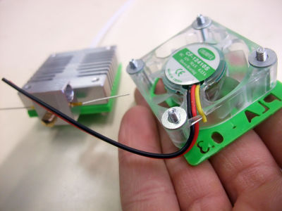
add the 4 M3 washers...
... and screw the elements in the hotend heatsink


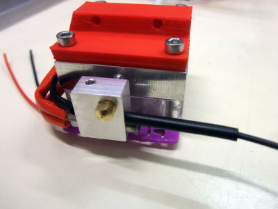
Cartridge heater
 x1 cartridge heater
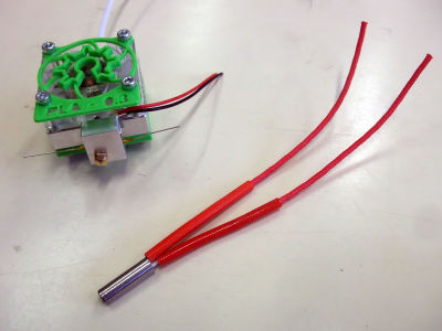
keep 10cm of the cartridge heater wires (and save 70cm for the cable harness)
insert the cartrige heater in the heater block so that the wires run along the fan wires
fix the cartridge heater in the heater block with a grubscrew


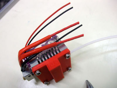
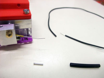
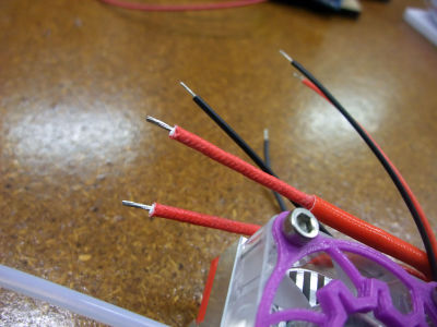
Wires
 x2 1mm ferrule
x2 heatshrink sleeve
x2 1mm ferrule
x2 heatshrink sleeve
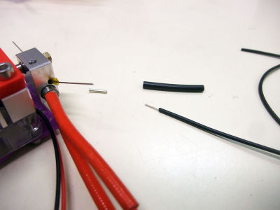
strip one extremity of a black wire
crimp firmly the wire on the thermistor extremity with a ferule
add the heatshrink sleeve over the metal part and heat it with a lighter
cut the black wire the same length as the cartridge heater wires
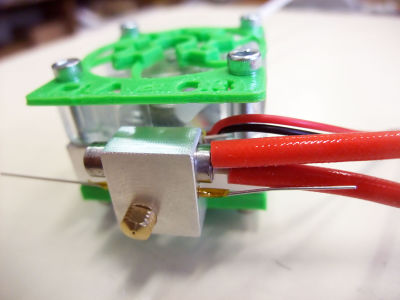
once again: strip one extremity of a black wire
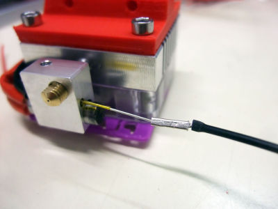
crimp firmly the wire on the thermistor extremity with a ferule
add the heatshrink sleeve over the metal part...
... and heat it with a lighter
bring the black wire together with the others...
... and cut it the same length as the others


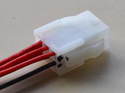
 x1 male casing
 x6 female ferrule
strip the 6 extremities of the wires
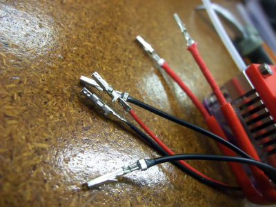
crimp one female ferrule on each extremity...
... and insert them in the male casing just like on the picture - 1: fan (red wire on top)
2: thermistor (wires' position doesn't matter)
3: cartridge heater (wires' position doesn't matter)
your hotend is almost ready! you still need to heat the hotend and tighten the nozzle in the heater block as much as possible but you first have to do the wiring...


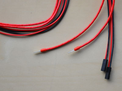
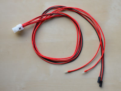
Cable harness
 x2 2 pin-wire with connector
 x2 cartridge wire (70cm)
 x1 female casing
 x6 male ferrule
 x2 end piece
shorten both 2 pin-wires with connector to 70cm
strip the extremities
take the 70cm cartridge wires that you've saved previously
strip the extremities
crimp firmly the male ferrules on the 6 wires
place the cartridge wires on the left of the female casing...
... and push the male ferrules until they get locked in the casing
place both 2 pin-wires with connector so that the red wire is upward
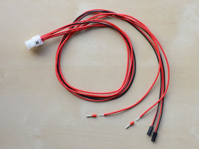
place both end-pieces at the extremities of the cartridge wires...
... and crimp firmly
your cable harness is ready to be connected


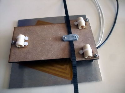
Bed-Plate
Heater
 x1 bed plate
 x1 film-heater
 x3 m3x30 countersunk
x3 m3 nut
x3 m3x30 countersunk
x3 m3 nut
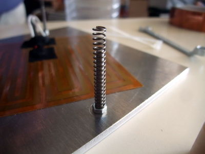
 x3 springs
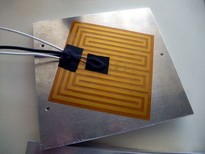
peel of the paper and stick the film heater on the plate
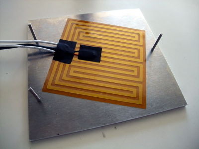
add the 3 countersunk m3x30
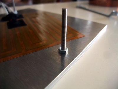
and lock them with m3 nut


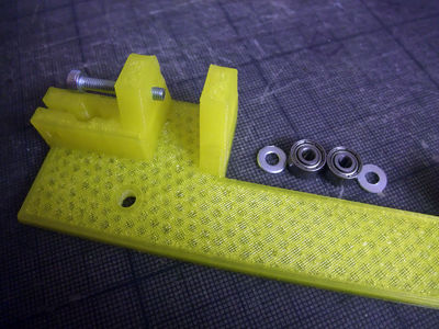
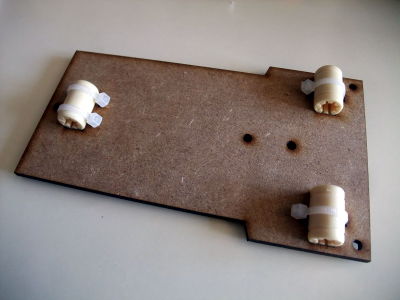
Y-carriage
 x1 y-carriage
 x3 linear bearing
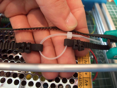
 x4 zip-tie
 x1 belt-clamp
x1 belt (600mm)
x1 belt-clamp
x1 belt (600mm)
 x2 m3x10
x2 m3 nut
x2 m3 washer
x2 m3x10
x2 m3 nut
x2 m3 washer
 x3 m3 nylock
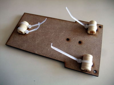
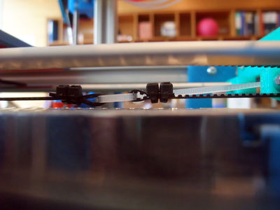
hold the linear bearing in place with zip-ties
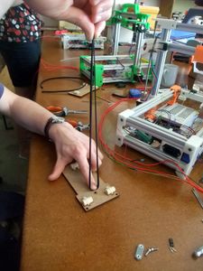
clamp the belt in the middle of it's length
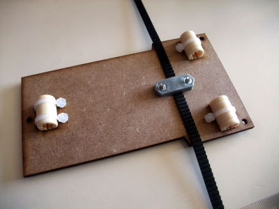
try to clamp it on the middle of the belt-clamp too
add the three m3 self locking nut (nylock) and tighten them a little (real leveling will be done just after)


Wires
 x1 2pin housing
 x2 female crimp terminal


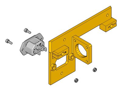
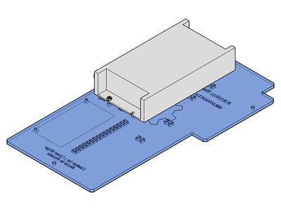
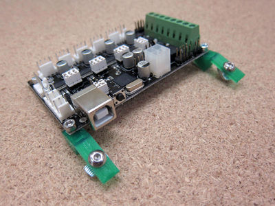
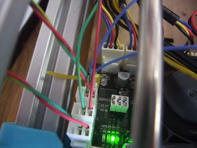
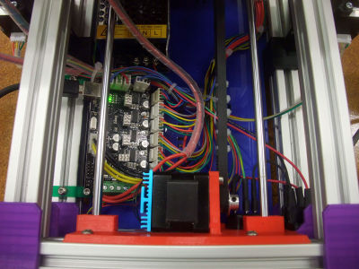
Electronic Board
Previous instructions for the AzteegX1 / Melzi
 x1
x1
 x1 board-mount
x2 m3x8
x2 m4x8
x2 t-nut
x1 board-mount
x2 m3x8
x2 m4x8
x2 t-nut
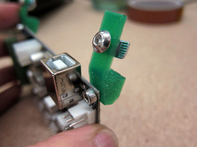
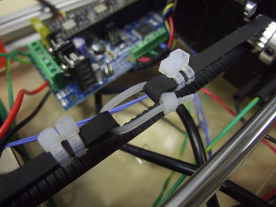
each board-mount is mounted to the board with a m3x8 and will use a t-nut to be held on the frame


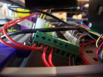
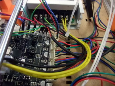
Wiring
Now lets plug everything to the board !

Look at the Minitronics_10 page, it is well documented and the wiring should be quite easy with the male/female connectors.
Setting the drivers current
- The drivers seems to use the same voltage reference as for a pololu (so we need to tune them between 0.4 - 0.5 V )
Depending of the motor and it's use :
- 1A Nema 14 (like LDO) : 0.4v for the axis and a little more (0.45v) for the extruder
- 1.25A and 9N.cm Nema 14 (HY0007) : 0.5v for the axis
- 0.8A and 15N.cm Nema 14 (HY0006) : 0.32v for the extruder, it may need a little more
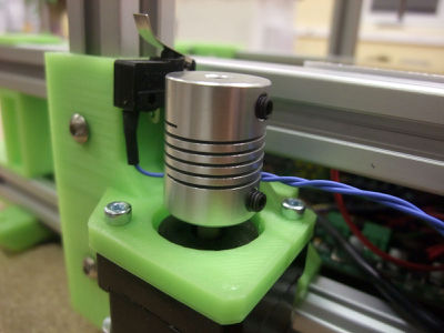
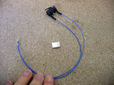
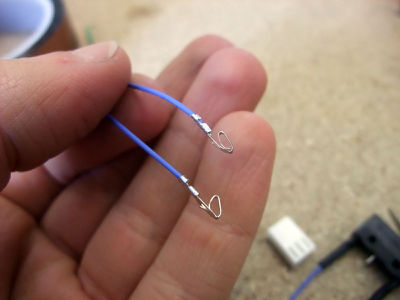
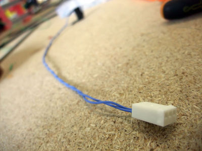
Endstops
- cut wires
- solder wires
- insulate
- crimp
- casing
- in place
- wiring
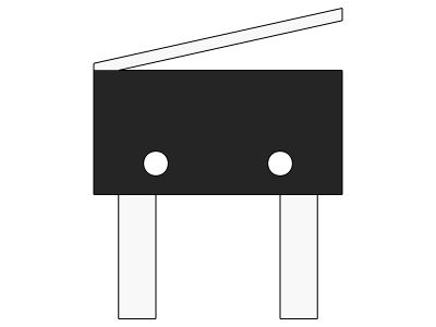
a switch wired this way is usually "normally closed", we will use this option
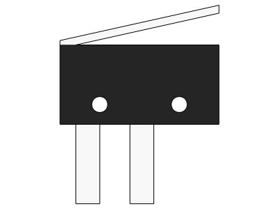
a switch wired this way is usually "normally open"
the firmware in the github repository is programmed for NC switches, but you can always change this value if needed


X
 x1
x1
glued on the side

Y
x1
x1 zip-tie
Y-endstop
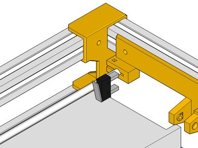


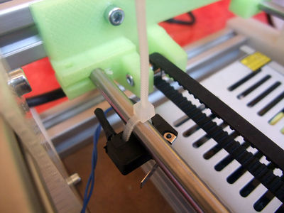
Z
x1
x1 m4x8
x1 t-nut
x1 zip-tie (or 2 m2x10 bolt)
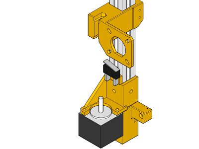
Z-endstop
endstops use the S and - pins of the connectors


Motors
- Y-motor
- Z-motors
- X-motor
- Extruder-motor
Hotend(s)
- thermistor (blue 75cm)
- heater (red 75cm)
- fan : on a 12v pin (must be always on)

Fans
- printed-part cooling fan: if the hotend's fan is alway on, this one is controlled by the electronic board via the "cooling fan" screw terminal (turned on by sending Mcode "M106 Sxxx" (xxx being between 0 and 255), turned off by "M107" but Slic3r automate this)
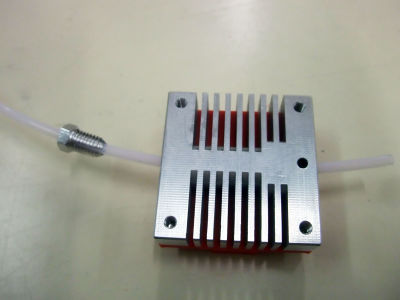
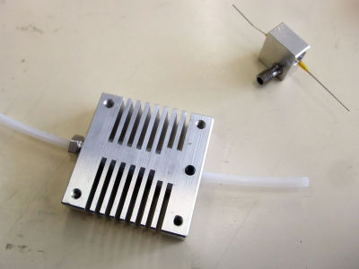
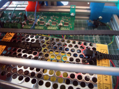
- Cooling the Minitronics_10's PCB is mandatory according to RichRap in RepRap Magazine 2:
The PCB is used as a heatsink and must be cooled from the underside with a 40mm fan or bigger, this is important to do with such a compact board.

Bed-Plate
Finish by this one, as it is moving, the wires need to be above all the other wires.
- thermistor
- heater element (the two thicker wires)
tip : you can hold the bed in the front profile while wiring the cables
-/+
It may be a little messy at first but once finished everything is tidy and protected in the base of the machine :)
another example


Tidying
- spiral wrapping band : for the wires that came out of the base.
(image)
Y-axis
 x2
x1 (with 32cm green wires for y-endstop)
x6
x2
x1 (with 32cm green wires for y-endstop)
x6
Slide the smooth rods through one side
then through the Y-carriage
and finish on the other side
The Y-motor was centered by the rear-foot-right, to align the Y-idler too check that the carriage run smoothly. By moving it will tend to center the Y-idler (or look that it seems at an equal distance from each front-foot. Once satisfied you can lock the Y-idler in place.

Make a loop at each end of the belt with zip-ties (pay attention to the orientation of the zip-ties)
pass it through the y-idler
and y-motor
why the orientation is important
Tighten the belt by closing the loops with zip-ties, then trim everything (video of belt tensioning [2])
fix the Y-endstop on the smooth-rod with a zip-tie or glue it on the front-foot side


Tape (5-10 min)
- Kapton (polyimide) or blue tape (= outside masking tape, uv resistant usually with acrylic adhesive, PLA stick well to acrylic)
<videoflash>MdCMMt7siy4|640|480</videoflash>
Making the bed parallel and zeroing
The Z-zero is made when making the bed parallel to the nozzle.
- Start by roughly makin it parallel
- then move the nozzle to the lowest point
- and adjust the 3 screws to move it regarding that height (by turning them until the homing move stop lowering the bed)
- repeat on each corners so the zero is exactly when the nozzle stop touching the bed (true for the four corners+center)
- I like to start with the Y direction with the two bolts, then with the remaining one
<videoflash>35Xv_R8U_hU|320|240</videoflash>
Here is a video to show what I mean by "the homing move stop lowering the bed"
<videoflash>rjIMmzltyLQ|320|240</videoflash>
"Bad" (the bolts need to be tightened)
- Once the plan is set from left to right you can check front/end


- after that it's supposed to be parallel but may need few more tweaks that will be revealed by observing the first layer of a print
Software side
- Skeinforge : you will only have to add a little offset (altitude), to have the desired height for the first layer, usually the same as your layer height.
- Slic3r : leave z-offset at 0, it will add one layer height automatically (you still may have to adjust it slightly to fine tune the Z-zero, depending on where your endstop have been glued).
Another advantage of that : by moving to the center of the bed from the zero height, the nozzle is also wiped by the side of the bed from any purged plastic ;-)
Go go go first print !!!

This article will probably help you along your first print :)
http://www.sarfata.org/3d-printing/2013/04/First-Steps-In-3D-Printing-With-Foldarap/
Also have a look at the User Manual