SevenSwitch 1.2
|
English • العربية • български • català • čeština • Deutsch • Ελληνικά • español • فارسی • français • hrvatski • magyar • italiano • română • 日本語 • 한국어 • lietuvių • Nederlands • norsk • polski • português • русский • Türkçe • українська • 中文(中国大陆) • 中文(台灣) • עברית • azərbaycanca • |
Release status: working

| Description | General purpose DC switch
|
| License | |
| Author | |
| Contributors | |
| Based-on | [[]]
|
| Categories | |
| CAD Models | |
| External Link | (none)
|
The SevenSwitch is a general purpose DC switch, useful for operating heated beds, heaters, fans and similar devices by 5 V operated electronics, like Generation 6 Electronics, RAMPS, Sanguinololu, Generation 7 Electronics and similars. The only input needed is a 5V signal. It's fast enough to run at 80 kHz PWM, strong enough to switch up to 15 Ampéres and allows voltages of up to 30 V, including 12 and 24 Volts.
The design follows that of the Gen7 Board, so it's easily do-it-yourselfable. You find sources in the Gen7 Github repository, including release documents (PNGs, schematics & layout PDFs).
Contents
Variants
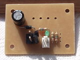
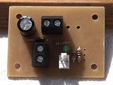
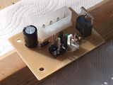
Depending on your requirements you can equip the SevenSwitch with a Molex KK156 (pictures to the left) or a screw terminal device connctor (pictures to the right) for the device connector and a disk power connector (upper pictures) or a screw terminal (lower pictures) for the power supply, making a total of 4 possible connector variants:
|
|

|

|

|
How to get it
PCBs
Get SevenSwitch PCBs from RepRap DIY (Traumflug's outlet).
If you want to make them yourself you can find production files in the release documents folder of the Github repository and manufacturing instructions on the Gen7 main page. If you want to sell excess copies, plase ask Traumflug for a commercial license.
Components
The easiest way is to get a SevenSwitch Parts Kits from RepRap DIY (Traumflug's outlet).
Parts Lists
If you don't want to order a kit and want to collect all the required components yourself, here's a list of all parts. To assemble or verify these lists, open the layout with gEDA/PCB and export a "BOM".
Electronic Components & Connectors
This list is ordered to match the recommended order of assembly.
| Name | Count | Designations | Vendors | Remarks | |||
|---|---|---|---|---|---|---|---|
| Resistor 10 Ohms | 1 | R1 | Reichelt | RS | |||
| Resistor 560 Ohms | 1 | R2 | Reichelt | RS | Digi-Key | Mouser | Bright indicator LED on 12 V operations! |
| Resistor 2.2 kOhms | Reichelt | RS | Digi-Key | Mouser | Alternative for also allowing 24 V operations. | ||
| Resistor 1 MOhms | 1 | R3 | Reichelt | ||||
| Diode 1N4004 | 1 | D1 | Reichelt | Digi-Key | Mouser | ||
| LED 3 mm Green | 1 | LED1 | Reichelt | Digi-Key | Mouser | ||
| Electrolytic Capacitor 100 μF | 1 | C1 | Reichelt | Digi-Key | Mouser | ||
| Molex KK100 2 Pin Header | 1 | CONN2 | Reichelt | RS | DigiKey | Mouser | |
| Cable Connector for the above | 1 | Reichelt | RS | DigiKey | Mouser | ||
| Crimp Contact for the above | 2 | Reichelt | RS | DigiKey | Mouser | ||
| Molex KK156 2 Pin Header | 0 or 1 | HEATER | RS | DigiKey | Mouser | 0 ea. if you choose the alternative screw terminal. | |
| Cable Connector for the above | 0 or 1 | RS | DigiKey | Mouser | 0 ea. if you choose the alternative screw terminal. | ||
| Crimp Contact for the above | 0 or 2 | RS | DigiKey | Mouser | 0 ea. if you choose the alternative screw terminal. | ||
| Disk Power Header | 0 or 1 | CONN1 | Reichelt | RS | DigiKey | Mouser | 0 ea. if you choose the alternative screw terminal. |
| Alternative to Device Header and Disk Power Header: 2 Pin Screw Terminal | 0, 1 or 2 | HEATER | Reichelt | DigiKey | Mouser | ||
| MOSFET IRLB 8743 | 1 | Q1 | RS | Mouser | |||
Assembly
- You'll need a soldering toolkit to do most of this.
- Read our Electronics Fabrication Guide if you're new.
- To find out which components to put where, have the layout on your PC screen available.
- PCBs fabricated with Voronoi paths need slightly more heat (about 10 deg Celsius more than usual) and a bit more patience. Letting the solder flow for 2 to 3 seconds is always a good idea.
- Start with the flattest parts, usually the resistors. This way, components won't fall out when you lay the PCB on it's front for soldering. Then continue with parts of raising height, connectors are usually among the last ones.
- The parts lists are sorted with that in mind, simply start at the top and assemble towards the bottom.
- To ease soldering of headers or similar components, you can put a small drop of cyanacrylate glue onto the component side before inserting them. As the PCB is single-sided, this won't hurt the solder point.
Assembly in Pictures
Click on the pictures to view them bigger.
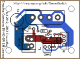
SevenSwitch 1.2 Layout. If you're unsure, always refer to this picture of the layout. The designators match those in the parts list.
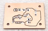
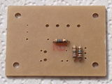
For best solder quality, tin all solder points before inserting components (the picture shows a v1.0 board).
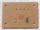
R1 has 10 Ω, so it's color-coded brown-black-black.
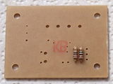
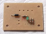
R3 has 1 MΩ, so it's color-coded brown-black-green.
R2 has 560 Ω, color code green-blue-brown or 2.2 kΩ, color code red-red-red. Use 560 Ω if you want to operate 12 V and want to have a bright indicator light, use 2.2 kΩ for switching 24 V.
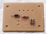
D1 is a diode, so you have to take care of polarity for the first time. Diodes have a white ring on the housing, which must end up closer to the boards boundary.
LED1 is a Light Emitting Diode, so direction matters. The longer of it's legs is +, which happens to go into the upper hole. You can also compare with the + sign in the layout.
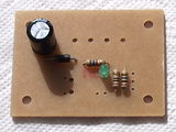
C1 is an electrolytic capacitor, which also has a polarity. It's housing has a white stripe, which is minus (-) and goes to the upper hole. Like with LEDs, the longer leg is +. Again, compare to the layout.
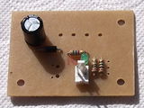
This header is for the connection to the controller electronics. The latch goes towards the center of the board.
This is the standard device connector. It allows plugging the device quickly and without fear of wrong polarisation. It's also limited to about 7 Ampéres. Don't save on solder, because all current goes through these two pins.
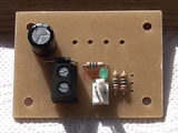
This is a screw terminal as device connector. There are four holes, use the ones that fit. Allows initially quicker wiring and up to about 15 Amps. Again, don't save on solder.
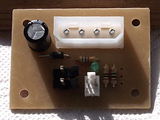
The standard power supply connector ist the same as the one used for PC disk drives, so it accepts the plugs available on a PC power supply directly. Make sure the campfered corners point towards the center of the board and don't save on solder.
If you prefer a screw terminal for connecting the power supply, solder it into the same holes. As you see, the left two holes are the ones to use. Don't save on solder.
Finally, insert the MOSFET. As you can see, the metal back goes to the outside, the part number towards the center of the board. Don't save on solder. After that you're done.


Setup
These steps show how to get from a soldered mainboard to a working one.
Power Source
The SevenSwitch is powered by a Molex 4-pin connector, like it's found in PCs. If you use a PC power supply, simply insert a connector that fits. It can be the same supply you use for your remaining electronics or a separate one.

- It's sufficient to connect one of the GND pins.
- It doesn't matter what's on the fourth pin.
- With a screw terminal, the left connection is for 12/24 V, the right one is for GND (obviously, as these are the corresponding spots).
Powered Checks
Before connecting a SevenSwitch to a controlling electronics, it's a good idea to do some tests. For these tests, connect the power supply and turn it on.
No smoke? Great!
- Test 1
- Neither of both pins going to the controller should have any voltage ( < 0.1 V). If you had 12 V here, you'd damage your ATmega.
- Test 2
- Do a dry run. Tip the signal (right) pin with 5 V. The LED should light up immeadiately and go off as soon as you remove these 5 V. In case these 5 V come from a different power supply, you have to connect the GND to the left of the signal pin to this supply, too.
- Test 3
- Do the same with a device connected, e.g. a fan or a heated bed to the device connector. Should work just as fine, with the device also turning on and off.
Signal Source

The picture shows where to connect the GND and the signal pin. The grounds on the signal and the Molex 4-pin power connector are connected together on the board. However you can use an independant power supply different from your main system as long as the two grounds are tied together or the supply ground can float to your main system ground. There is no optical or other isolation. Remember that the fan or heater is driven in a low side switch configuration so it will have the 12V supply connected even if it is not switched on.
Prepare your Controller Firmware
How to prepare your controller electronics obviously heavily depends on your type of electronics (Gen7, Gen6, RAMPS, Sanguinololu, ...), your type of firmware (Teacup, Marlin, Sprinter, Repetier, ...) and the pin you've choosen to fetch the signal from, so I can't give detailed instructions here. Generally, the signal pin for the SevenSwitch is handled like any other pin, no special treatment needed.
The signal pin should be a digital I/O pin, preferably a PWM-able one. If you use an analog pin, make sure the firmware configures it as a digital pin.
If you've figured out how to connect your combination of electronics, firmware and signal pin, please insert your description as an example here.
A Word of Caution
If you bring the SevenSwitch to it's edge, the MOSFET will become hot. Hot, like 60° C or more. The MOSFET will survive more than your fingers, in tests it got up to 110° C without blowing anything.
Circumstances raising MOSFET temperature:
- Higher PWM frequency.
- PWM loads of closer to 80%.
- (no, actual current almost doesn't matter, as the MOSFET can withstand a lot more than the connectors)
Countermeasures:
- Lower PWM frequency. For example, comment out FAST_PWM in Teacup's config.h.
- Use a bang bang temperature control. For Teacup, also use BANG_BANG_ON = 255.
For diagrams, see Gen7 Research. SevenSwitch uses a 10 Ω signal resistor.
Specials
24 V
To switch 24 V with a SevenSwitch, replace R2 with 2k2 ohms (or remove it entirely). It'll still work on 12 V then, but the indicator LED will be much dimmer. Choosing R2 is also shown in the assembly instructions above already.
Non-12-V-Voltages in general
The SevenSwitch will happily switch any voltage between zero and 30 Volts (yes, also a voltage lower than the signal voltage). The only part which might need adjustment is R2, the LED pre-resistor. Use 2.2 kΩ for all voltages. On lower voltages the LED will be dimmer, which can be compensated with a smaller R2. If you have no replacement resistor handy, you can remove R2 entirely and loose the LED's functionality. The switch works without indicator LED just fine.
Application Examples
Stemer114 describes he connected his SevenSwitch to a Sanguinololu in the RepRap forum.
Upgrading to v1.2
If you have an older SevenSwitch, it's pretty simple to upgrade it to a v1.2 one. You need an 1 MΩ resistor between gate of the MOSFET and GND, which can be added on the solder side. Like this:

History
SevenSwitch 1.2 has the following changes compared to SevenSwitch 1.1:
- Additional 1 Mohms pulldown resistor on the MOSFET gate to turn the MOSFET off with no signal connected.
- The footprint for screw terminals on the power supply side was removed again, as these fit just nicely into the holes for the disk power connector.