Gear design
Contents
Art of Illusion Cog Gear Design
Index
Gear Design Basics
If you're an engineer, this is probably old hat - but read it anyway so you can correct my mistakes. Gears are generally round, with teeth. The number of teeth and their shape are more important than is initially apparent.
teeth shape
They need to mesh, and so need to be the same height. The incoming gear teeth must contact at the right place, and only at the right place - which is why they're a funny "involute" shape and not square or little triangles.
The tip of the gear teeth are not supposed to go all the way down into the opposing trough. If that happens the next incoming tooth tip smacks into the top of the opposing tooth. Contact between teeth is notionally along a point just over half way (typically a 1:1.25 split) up the teeth, and this is called the 'Pitch Line'. The bit above the pitch line is called the 'Addendum', the bit below it the 'Dedendum'. The angle of tilt on the faces of the teeth is called the 'Pressure Angle' and is normally about 20 degrees.
The distance between the centre of one tooth tip to the centre of the next is called the 'Pitch'. You want the pitch on touching gears to be as close as you can get it. Ideally, the pitch is 2.25 times the height of the teeth. If the height is the same on both gears, then the pitch is the same, and if the width, height, and pitch are the same, then don't they have to be the same diameter?
The forces between the contacting teeth have to be even and consistent, or vibration builds up. So does noise and wear. These problems are made worse by teeth flexing around, so with a relativley soft plastic we're going to have interesting problems.
Number of Teeth
To provide mechanical advantage, contacting gears have different numbers of teeth. A little gear driving a big gear will increase the torque and slow down the speed of rotation. Gears typically have prime (or at least co-prime) numbers of teeth. This is so that the same teeth do not always press against one another, so distributing wear, dirt, oil and squashed fingers etc. evenly across all gear teeth involved.
Bad: 15 and 25 teeth. A bump on the large gear always hits the same 3 teeth on the small gear, creating uneven wear; in this same example a bump of the small gear always hits the same 5 teeth on the large gear. To calculate this first find the Greatest Common Divisor (GCD) of each gear tooth count. e.g. GCD(15,25)=5; then divide this result into the number of teeth in question. E.g. 15/5=3 and 25/5=5.
Good: 16 and 25 teeth. A bump on the large gear (eventually) hits every tooth on the small gear, wearing them all equally.
An even uniform gear wear is achieved by ensuring the tooth counts of the two gears meshing together are "relatively prime" to each other; this occurs when the Greatest Common Divisor (GCD) of each gear tooth count equals 1. e.g. GCD(16,25)=1
FDM Restrictions
Gears made from ABS or Polymorph need to be sturdily constructed in order to survive. Little pointy bits will soon be broken off when the mechanism (inevitably) jams. Wear & tear is a fact of life, and so plenty of extra material is needed. In short, your gears will be chunky and inaccurate.
We make the gears fairly thick, as the larger contact area lowers the contact pressure and hence the wear. We use smooth curves rather than angular jumps, partly because the FDM machine can't be sufficiently accurate, and partly because they'd introduce points of wear.
To lower the mass of the plastic used, we put strategic cut-outs in the gear to create spokes. Everything is still kept nice and chunky to avoid flexing. Flexing leads to wear and noise.
Although the FDM processes available will produce a theoretical accuracy of 0.1mm, the smallest individual feature that can reliably be reproduced is 0.6mm. So that sets the absolute minimum width of a gear tooth with no shaping whatsoever.
Finally, we need to attach some of the gears to a shaft. As the plastic is not that strong, this needs big, chunky collars to hold big grub screws, or in the case of this example a recess to hold a nut.
Designing Cog Gears In Art Of Illusion
The gears described here are the ones used to raise and lower the turntable. The larger gears attach to studding, which goes up and down when turned in a captive nut on the RepRap carriage. The smaller gear is slipped on to the shaft of a stepper motor and turns the other 3 gears simultaneously. Because the accuracy provided by the thread is very high, and the amount of slack in the gears produces a relatively small error in displacement of the platform, some play in the gears is acceptable. In other situations this may be a big problem, and cunning solutions known as anti-backlash gears are required.
To make life easier, AoI has a "Cog" script, which I (VikOlliver) adapted from a "Star" script kindly created for me by Francois Guillet.
To load it, go to AoI's "Tools" menu, and select the Scripts & Plugins Manager. Under the "Install" tab are many useful bits. In Scripts/Tools you'll find a "Cog" script. If it's not there you may have installed it already.
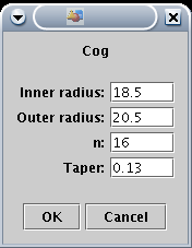
To actually design the gears requires a fair bit of thought. You need to figure out how big they are going to be, and determine a suitable tooth size. The example teeth are 3.85 mm pitch. The big gear has 79 teeth, the smaller gear 16 teeth; 79 divides by 16 very poorly, so wear should be evenly distributed. Use elementary geometry to figure out the diameter of the gears.
The height of the teeth should be just over half the pitch, and these are 2mm high. So when entering the Cog script parameters, the outer diameter is 2mm larger than the inner diameter.
The taper of the side of the teeth is defined in the Cog script as a ratio. A process of blind experimentation determined that a value of 0.12 - 0.13 seemed to be about right. Once all the parameters are entered in, the gear can be created. This results in a 2D path that looks remarkably like a gear.
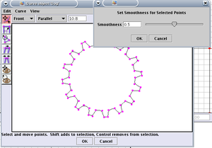
Having made the basic shape of the cog, we need to shape the rather square teeth. This is done by editing the cog shape. To do this right click on your cog in the objects window and select "Edit Object". When the Curve Object window appears pull down the "Edit" menu and click on "Select All". Next pull down the "Curve" menu. When the "Set Smoothness for Selected Points" control appears use the slider to a value of 0.5 and click "OK". You will clearly see the perimeter of your cog take on a nice smoothed appearance. If it is suitable to your purposes click "OK" on the "Curve object" window and you will be back to your main display window. The cog can then be extruded using Tools/Extrude to the required thickness; 6mm seemed about right for this one, with the central cog being over twice that high.
Once they're extruded and converted into a triangle mesh, edit the mesh using the editor's Edge mode and close the ends up. Just drag the mouse to select all the edges on one end, then use Tools/Close Selected Boundary.
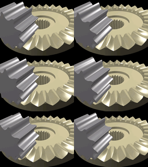
AoI Rendering of a finished set of gears to raise and lower the RepRap turntable
The larger gears in the illustration above have been pierced to save plastic, and a central hole to allow a piece of M5 studding to be inserted through them. A sturdy collar with a hexagonal well has been added, which traps an M5 nut. Adding a large M5 washer and nut to the other side, and doing the nut up tight securely traps the gear in place.
The smaller gear is pierced with a 4mm hole into which a piece of PVC tubing is pushed. The gear is then slipped over the 3mm shaft on a stepper motor, compressing the tubing and forming a snug, centred friction fit. Here is what they looked like after fabrication. They are used the other way up to the modelling illustration, it being quicker to fabricate gears with their flat face oriented at the bottom:
the hole in the middle of the gear
There's typically some sort of shaft that passes through the center of the gear.
Sometimes we want the gear to spin on the shaft (such as when we have "stacked gears" [1], [2]). So a smooth hole -- perhaps a hole large enough for a bearing.
But most of them time we want the gear rigidly attached to the shaft, so they turn together. Currently the most popular things to do at the center of the gear are:
- A hole and a slot that traps a wing-nut "inside" the gear. Adrian's Geared Extruder#The gear drive, RepRap Universal Mini Extruder, [3]
- a hexagonal well which traps a hexagonal nut or the head of a hex-head bolt; add a washer and nut to the other side to rigidly mount the nut to the bolt. Wade's Geared Extruder, Herringbone Extruder Driver, File:GregFrostPrusa3ImprovedWadesGears.jpg, [4], File:Hub-gear.bmp, File:Build67.jpg
- grub screw ... File:GregFrostPrusa1Pulleys.jpg, [5], File:Drive-gear.bmp, File:Pulley.bmp
- What am I seeing in File:Universal Paste Extruder.jpg ? or in [6] ? File:Build135.jpg ?
(I'm sure clever RepRap researchers will continue to come up with alternatives).
References
Basic Gear Formulas http://www.pic-design.com/tech/gear_form/gear_form1.htm
How gears work http://auto.howstuffworks.com/gear.htm -- Main.SvendSrensen - 16 Nov 2005
-- Main.ForrestHiggs - 06 Sep 2006
Further reading
Michal Zalewski. "Creating spur gears", part of the "Guerrilla guide to CNC machining, mold making, and resin casting". A lot of usually overlooked details goes into designing "Normal" involute gears; this is one of the few approachable gear design documents that gives those details.
taulman. How to make a high resolution NYLON, ABS and PLA nozzle for a 3D Printer". makes tiny gears.
Jon Watte. https://github.com/jwatte/gears (via the Mechanics Q&A site ) A Java program that asks a few simple questions, then generates G-code and SVG files to produce standard Metric and standard Standard(?) gears.
For those of you who think you know everything about gear design:
Ognyan Alipiev. "Geometric design of involute spur gear drives with symmetric and asymmetric teeth using the Realized Potential Method" [7] [8]
"Wrap Your Head Around These Gears". includes "paradoxical gears": side by side gears that turn in the same direction (!). When two gears mesh, isn't one supposed to turn clockwise while the other turns counter-clockwise?


