PCB Heatbed/ua
|
English • العربية • български • català • čeština • Deutsch • Ελληνικά • español • فارسی • français • hrvatski • magyar • italiano • română • 日本語 • 한국어 • lietuvių • Nederlands • norsk • polski • português • русский • Türkçe • українська • 中文(中国大陆) • 中文(台灣) • עברית • azərbaycanca • |
Release status: working

| Description | PCB Heatbed
|
| License | unknown
|
| Author | |
| Contributors | |
| Based-on | |
| Categories | |
| CAD Models | [[1]]
|
| External Link |
Contents
WARNING
"WARNING!!! Be careful where you buy PCB heatbeds from!! There is one very important requirement - the heatbed must be etched directly from 35um copper clad! ASK YOUR SELLER!!! If the board is plated, as it's normally done, the manufacturer cannot guarantee the final thickness of copper or the evenness of the copper around the board. If it is uneven, the heat won't be evenly distributed around the board or the board won't have a high enough heat output overall.
Your biggest warning sign is plated holes! Plating of holes requires copper plating.
About
The original PCB Heatbed MK1 was developed by Josef Průša.
- 200 mm x 200 mm active heated area.
- 209 mm center-to-center mounting holes (outside the active area).
- 214 mm x 214 mm total PCB size.
"I was working on this idea for nearly six months, inspired by neufeld.newton.ks.us/electronics/?p=864".
Where to get it
The .brd file is available here: [[2]]
Mechanical drawings for designing mounting plates/etc (if desired) are here: [[3]]
(Please note that I dont get any provision from these :-)) Manufactured PCBs can be found here:
Refer to the RepRap_Buyers'_Guide [[4]]
Printing
Previously the accepted method was to cover the PCB heatbed with kapton tape, degrease it and print. An alternative method that has become popular (as of January 2015) is to use a sheet of 3mm borosilicate glass, held using bulldog clips (see the Discussion tab). Adherence of the printed object to the glass is helped by spraying the clean glass with hair lacquer (the "extra strength" type).
ABS temperature range: 100-110°C
PLA temperature range: 50-70°C
These ranges of temperatures are indicative only, you'll have to test and see what works best for your printer/filament/hotend setup.
MAKE SURE YOUR Power Supply HAS 10 MORE AMPS SPARE!!!
Mounting
Known working solution, I (prusajr) use is Glass sheet (3mm) with glued on cork standoffs and on top of that is glued the heatbed. http://www.flickr.com/photos/prusajr/5410919911/ http://www.flickr.com/photos/prusajr/5410919707/
When mounted only using the four corners, the inherent warp of the pcb can be a problem, hence it is better to use the cork mounting system above (as the piece of cork in the centre helps to keep the pcb flat). Magnets can be used in replace of the cork, this makes the bed removable. However, I (mooneyj) have only tried this on a darwin type printer (where the build platform only moves in z). During fast printing, the darwin vibrates and it seems the heatbed magnets slide over each other slightly. The acceleration of the y axis on a mendel may cause the magnets to slide also. Perhaps a hybrid of magnet and bolt mounting would work well?.
The current standard (as of January 2015), however, is to simply place a square (200mm x 200mm) piece of glass on top of the heatbed, and affix it on the four sides with bulldog clips. The clips will not melt under pressure, and sufficiently hold the glass to the bed. This makes removal easier for cleaning as well.

Sides
The PCB heatbed has two sides, one with the copper traces (bottom side) and one without (top). On older versions of the PCB heatbed only the side without traces carried a silkscreen. Currently (as of January 2015) PCB heatbeds are silkscreened on both sides.
Previously, printing on the top side was considered to be safer as the copper traces could be damaged if the print head would collide with the heatbed surface (if for example the Z-min endstop malfunctioned). Obviously if a piece of glass is used as the print surface, it protects the PCB copper traces. However, make sure your heatbed mounting springs are not too strong to prevent damage to the glass in case of an accidental collision.
Note that the LED, resistor and wire connections are also liable to accidentally collide with the print head.
Again, the current standard (as of January 2015) when the PCB heatbed is used with a piece of glass as the build surface is to mount the PCB heatbed with the traces up. This improves heat transfer to the glass and the PCB heats up faster.
Connection
Optional LEDs
The LEDs are optional, but if you choose to use the LEDs you MUST install the resistor.
'Parts'
2 x Surface Mount LEDs
1 x 1K ohm Surface Mount Resistor
Mount the LEDs in different directions (polarity) so that one of the LEDs will light up regardless of the board's polarity. You can use a single LED if you are certain of the polarity.

Electronics
RAMPS
See RAMPS1.4, RAMPS1.3, or RAMPS1.2 depending on your version.
Sanguinolou The MK2 PCB heatbed heats up to 110C when powered through the heated bed connection on Sanguinolou. Your power supply should be 300W and you should ensure that the wires from your power supply to the Sanguinolou are capable of handling the total draw of 20A+. Using a 300W ATX power supply with the 4wire ATX dual 12V connector is working well for me.
N.B. It is recommended that you use a heatsink on your heated bed mosfet, it will get hot!
N.B. It is recommended that you measure the resistance of your board. I (evilB) didn't and blew up my Ramps 1.2 MOSFET because of a too high current. My measured resistance was 0.8 Ohm.
Troubleshooting (presumes 12v beds)
The heatbed is often the source of various problems in RepRap 3D printers. The following is a list of possible problems and how to correctly diagnose their cause and possible solutions:
T1) As soon as the PCB heatbed is turned on, my power supply switches off.
- D1) Check that your power supply can effectively supply 12V @ 15A or more. If you are using an old PC power supply, it may not be able to provide the required current, or it could need a balancing resistor.
- S1) Use a better power supply. See Choosing a Power Supply for your RepRap.
T2) My PCB heatbed never reaches the required temperature, or takes too long to reach the required temperature.
This is probably the most common problem with heatbeds that RepRap builders have to deal with. It can have various causes:
- D2a) Turn off your printer completely, and measure the resistance of your heatbed using a multimeter: it should not be higher than 1.2 Ohm. If it is higher than 1.2 Ohm, your heatbed will not get enough current and will not dissipate enough heat to reach the required temperatures.
- S2a) Return the heatbed to whomever sold it to you and make sure to get one with a proper resistance!
- D2b) If you have measured the resistance of your PCB heatbed and it is lower than 1.2 Ohm, you need to check the voltage across the heatbed terminals when it is heating up. If the voltage is significantly below, say, 11.7V, then again your heatbed will not get enough current and will not dissipate enough heat to reach the required temperatures.
- S2b) Make sure you are using electrical cable with a proper gauge (14 gauge recommended) to connect the heatbed to the controller board. And again, make sure your power supply provides the proper voltage under load conditions. Change components as required.
- D2c) Make sure you have the PCB traces on the upper side of your heatbed!
- S2c) Flip the PCB heatbed if required.
T3) I have checked the temperature on the PCB heatbed and it does not provide uniform heating..
- D3) This is actually quite common and not a very serious problem as long as the variation in temperature is below +/- 3C between center and periphery. The corners will always be a little cooler, too.
- S3) Check the various PCB insulation methods listed below. They will minimize heat losses from the underside of the PCB.
The following video shows a PCB heatbed MK2 being heated to 60 degrees as seen by an infrared camera:
Thermal insulation
It's a good idea to insulate the underside of the heatbed in order to get a faster heat up time and a overall better thermal performance. For higher temperatures, an insulation might even be required.

Solutions found to work are:
- Cork plate.
- Cotton batting.
- Wool felt sheet.
- Rescue sheet, see e.g. Robert's Heated Bed ie the silver or gold rescue blanket used by hikers.
- Glass fibre soldering/plumbers/welding mat
- Silicon or teflon cooking sheet
FORKS (not done by Prusa)
MK2, MK2a
It's not successor of MK1 even with it's name. It's concurrent design. - Josef Prusa
MK2a Heatbed with minor changes by Tony from Think3dPrint3d
About the MK2a
I liked Josef's original design but wanted to be able to use through hole components, have the thermistor poke through the middle and for it to look good on the 'back' with the silkscreen that Josef designed on that side as well.
The MK2a has a few further changes:
- A mounting hole in the middle of one edge to allow for easier bed levelling, thanks to Nophead for this suggestion.
- Larger LED and Resistor pads to allow for 1206 size surface mount components.
- Much larger area to solder the current carrying wire, easily connect ribbon cable (such as with the Mendel90 heatbed connection). Also the through holes increased in size.
- The redundant pads on the non-heating element side of the board removed to prevent confusion. These are not electrically connected if the board is not plated (plated boards are bad for the reasons outlined by Josef Prusa above).
Further update of the MK2a
(by Tony from Think3dPrint3d)
In order to make ribbon cable easier to use we have made the following changes:
Holes in the extended solder pads

This allows for IDC compatible pin headers to be used

This in turn makes plugging in a heated bed wiring loom very easy

Where to get it
The MK2 .brd file is available here: File:PCB heatedbed Mk2.brd[[5]]
The MK2a .brd file is available here File:PCB heatedbed Mk2a.brd
Manufactured MK2 PCBs can be found here:
MK2A, MK2B, MK3 - TaoTac.com VN
Alfa-Tech3D MK2B (DK, Worldwide)
Think3dPrint3d (UK, Worldwide)
http://www.3distributed.com/products/mk2-heated-bed-1
MK2a, MK2b (214x214mm, 314x214mm and 326x326mm) from ThingiBOX
Reprapdiscount MK2 and MK2a eBay
Uw3Dprinter.nl MK2 (NL,BE,DE,FR)
RepRap Portugal MK2B Red and Black
opensourcehardware.it (MK2B, MK3-ALU, MK3 300x200)
www.hta3d.com (MK2A 300x200, MK2B, MK3-ALU, Borosilicate tempered glass and more!!)
orballoprinting.com MK3 MK2B wolrdwide shipping
Printing
MK2
Although you can print directly to the bed covered in polyimide tape, no PCB is perfectly flat. It is recommended that you follow the directions in mounting, below, for better results.
Mounting
MK2
The MK2 board can be mounted either side up and is designed to be mounted as Josef describes:
http://josefprusa.cz/pcb-heatbed-final-mounting-and-wiring-solutio
The holes in the 4 corners to attach the heated bed MK2 to the top print plate are not suitable for M3 bolts though! Use M2.5 instead.
The glass protects the tracks from a head crash and is easily swapped out.
The board dimensions are identical to the MK1 design.
Insulation between the board and the thick plate should improve heat-up times and reduce energy consumption. An example is here:
http://reprap.org/wiki/Mendel_heated_bed#Thermal_Insulation
Caution, I have not tried this with the temperatures that the PCB bed can reach!
MK2a
The MK2a has a central mounting hole on the front side to allow for three point mounting. This is much easier for bed leveling in comparison to 4 point mounting. First level the side with two holes and fix in place, then level the side with one hole. A glass plate is highly recommended to provide a truly flat surface and rigidity.

Sides
MK2
The PCB still has a side with the traces on and a side without but now the silkscreen is on both the top and bottom, this makes it look good even when 'upside down' under a layer of glass. The LED, resistor and power wires can be mounted on either side of the board, with either surface mount or through hole components. If you are using through hole be careful when soldering not to interfere with the glass and introduce a gap between the glass and the PCB. If the MK2 board is made properly without copper plating then be sure to only solder the LED and resistor to the same side and the tracks. This problem is solved in the MK2a by removing the pads on the non connected side.
MK2

MK2a

MK2b Dual Power


There is a central hole in the board and it is sized so a small thermistor (for example the EPCOS one: http://uk.farnell.com/jsp/search/productdetail.jsp?CMP=i-ddd7-00001003&sku=3878697 ) will fit though it allowing contact directly with the glass. todo: test efficacy of using heat sink compound to better thermally couple the thermistor to the glass

Connection
Polarity doesn't affect the PCB, however the LEDs have a polarity.
MK2
There are pads and un-plated through holes for connecting the power wires. Ensure that the wire you use is thick enough for 10A, and solder it to the pads on the track side of the PCB. It is a good idea to think about strain relief so your moving build platform does not flex the joint, this can lead to failure of the joint over time. I recommend routing the wire from the heated bed to strain relief on the thick sheet before routing it to your controller/power supply. todo: get pictures of strain relief
MK2a
The pads to solder onto have been greatly increased as shown in the picture below. The picture shows the wires prepared for soldering routed through the holes for extra security. This does not remove the need to use proper strain relief.

MK2b Dual Power
As you can see in the pictures below depending on the voltage you want to use you have to use different solder pads, but it's written on the PCB which pads have to be used for which voltage.


MK2i The MK2i is connected just like the MK2a heatbed.
Optional LEDs
MK2
The LEDs are optional, but if you choose to use the LEDs you MUST install the resistor. Solder the components to the pads on the track side of the PCB. With the MK2, conventional wired parts can be substituted for the surface mount parts. If your MK2 board is made properly without copper plating then be sure to only solder the LED and resistor to the same side and the tracks. This problem is solved in the MK2a by removing the pads on the non connected side.
'Parts'
2 x surface mount (0805 size on the MK1 and MK2, 1206 size on the MK2a for easier soldering) or conventional through-hole LEDs. Install with opposite polarity so one or the other will light up regardless of the polarity of the power supply to the board.
1 x 1K ohm surface mount or through-hole resistor
MK2b Dual Power Technical Details
You can find the open source files here: http://forum.reprapdiscount.com/forums/oss/
- Dimensions 214mmx 214mm
- Laminate FR4 1.6+-0.15mm
- 2 layer, 35μm copper
- Red Soldermask - both sides
- White Silkscreen - both sides
- Power Input: 12V or 24v
- copper plated holes
- resistance between 1.0-1.2 ohm (12V) or 3-3.4 ohm (24V) (Sainsmart board came in at 1.8 ohm @ 12V/3.6 ohm @ 24V)
MK2i


The MK2i is a hybrid of MK2a and MK3 designs. It supports 4-point and 3-point mounting. There is a central hole in the PCB for a through hole thermistor such as EPCOS. There are also pads on top and bottom for an SMD or through-hole thermistor. The pads are on the top/bottom (in the center of the PCB, next to the hole) but the thermistor trace is on the top copper and routes again to the bottom for easier wiring, labelled "NTC". This design is versatile and much less tape is needed for strain relief on the thermistor wires.
The MK2i also sports an internationalized stencil on top and bottom. The stencil has new international symbols for "hot" and "hot - do not touch", as well as translations in English, Spanish, French, and German. The original CAD file also had translations in Chinese, Russian, Arabic, and Japanese - but it fails to export these character sets so they aren't in the final version.
The code is at https://github.com/Terawatt-Industries/mk2i and comes with a LBR library file. You should be able to have PCBs made from the MK2i Gerbers. It's probably feasible to make this by hand - as much as an MK2a PCB - except in this case you must have bottom and top layers if you want the thermistor wiring feature.
MK2 A4
This is my build. I always wanted a big bed, in order to be able to plot (yes, actually plot, with artistic purpouses) at least DIN A4 in size. So I built my prusa mendel big enough to be able to host such a HBP PCB. I'm no good with any PCB editor, so I made my files in a CAD program, and exported the result file into a dxf file. The file has several layers the names of which should make the information self understandable. Anyway I'll tell: the layers with number names represent the routing of the traces the width of which is the layer's name in mm. The design was basically copied from MK2a. The engineering was made with an evolutive algorithm developed by Damrod in grasshopper. The manufacturing was a bit faulty, but it works flawlessly.
- Dimensions 215mmx 315mm
- 1 layer 35μm copper
- resistance between 1.0 and 1.2 ohm

PCB Heatbed 200X300mm


The PCB Heatbed 200X300mm has a 100mm bigger built area then the regular MK2 heatbed and the overall outline is 214X314mm.
It has dual power mode optimized for 12 or 24V but you can also use everything in between (16V, 19V what have you) (Your printer controller will regulate the power to the heatbed in order to get your preset temperature.)
The core is regular 1.6mm FR4 PCB and the print surface is the same as regular heatbeds but with a metric ruler grid.
The connections to the heatbed is the same as the connections on the MK3 Alu. heatbed belov.
The PCB Heatbed 200X300mm is now available in the RepRap.me webshop.
- Dimensions 214mm x 314mm
- 1 layer 35μm (1oz base) copper
- Resistance between 1 and 1.3 ohm for the 12V
- Resistance between 4.5 and 5 ohm for the 24V
- 110 degrees Celsius possible for both 12V and 24V
- Running 24V on the 12V terminals will heatup the heatbed to 100 degree in only 2 minutes
- 180 degree Celsius max. temperature
MK3 ALU-Heatbed Dual Power
The Alu-Heatbed MK3 have features similar to MK2 and you can also operate this board with 12V or 24V.
- Heatbed with 3.2mm Aluminum Core. Print directly on the heatbed, no need for glass plate. It's a much lighter solution than PCB heatbed + glass, which makes it better for faster prints.
- Dual power supply. Operate at 12V or 24V. You can use thinner wires when operating at 24V.
- A central mounting hole on the front side to allow for three point mounting. This is much easier for bed leveling in comparison to 4 point mounting. First level the side with two holes and fix in place, then level the side with one hole.
- Large solder pads for multiple wires (ribbon cable) or a SMD pinhead connector can be mounted.
- Pads for SMD thermistor 1206
- Dimensions 214mm x 214mm
- 1 layer 35μm (1oz base) copper
- Resistance between 1.4 and 1.6 ohm for the 12V
- Resistance between 5.0 and 5.4 ohm for the 24V
- 100 degree Celsius possible for both 12V and 24V
- With 15V on the 12V terminals will maintain approx. 115 degree Celsius without regulation
- Running 24V on the 12V terminals will heatup the heatbed to 100 degree in only 2 minutes (Your printer controller will regulate the power to the heatbed in order to get your preset temperature.)
- 180 degree Celsius max. temperature
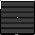
 Bottom side (Do not print directly on this side)
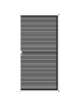
 Top side (Printing side)


When connecting the heatbed in the 12V setting it is important that you connect solder pad 2 and 3 directly on the heatbed.
Recommended NTC: EPCOS - B57621C104J62 - THERMISTOR, 100K "or whatever thermistor you normally use."
Where to get it
Alfa-Tech3D
www.RepRap.me
www.cubic-print.de
(Cubic-Print currently only offers the version of the bed thats needs a wired thermistor. The SMD pads are solely for SMD LEDs and their resistor.)
TaoTac.com
MK3 (214x214mm and 314x214mm) from ThingiBOX
MK2a layout in SVG-format
There's an SVG-version (Inkscape) of the MK2a-layout.
For the toner transfer method and people that only have a printer for letter/DIN A4 there's a version with two separated parts. Because the parts only have few electrical contacts between them, they easily can be ironed next to each other, fixing the needed bridges with etch resistant paint before etching.
MK2A in SVG
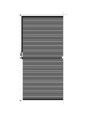
Printer friendly Part I
Printer friendly Part II
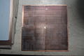
Toner transfered and ready to etch
The etched board


(You may follow the complete process here: Etched_heatbed_construction)