Prusa I3 confusion
Posted by awdorrin
|
Prusa I3 confusion December 31, 2015 07:50PM |
Registered: 8 years ago Posts: 26 |
I got a Prusa I3 clone from eBay for Christmas. Gt2560 controller, Mk8 extruder, Mk2A heated bed, Marlin firmware. Using Slicer and Pronterface under Windows 10, 64bit.
Assembled it over a few days, and managed to get a couple decent prints out of it using PLA on bare glass.
Then, suddenly I couldn't get prints to stick to glass, so I used blue tape, got a couple more decent prints, and now I can't get the PLA to stick to tape.
I've double checked the Z height at all 4 corners and the center, can barely slide a piece of paper, which I think is correct.
However, I am starting to doubt that the thermistors are working properly. The first few days the bed thermistor was reading 26C at room temp, now it is reading 40C at room temp. (Room temp is 70F / 21C)
I am not sure what to do next, and am hoping that someone here may have suggestions, or pointers on where to look for more info. ( I've been searching for 2 days online)
I have not downloaded the marlin firmware yet. Maybe there are there adjustments for thermistor calibration, but I haven't stumbled across any documentation about that yet.
Maybe I'm chasing the wrong thing, but after spending the last 10 hours today trying a dozen different things, I'm completely stumped.
Thanks for any suggestions
-AL
|
Re: Prusa I3 confusion December 31, 2015 09:40PM |
Registered: 9 years ago Posts: 1,873 |
The thermistor should be within a degree or two at room temperature, and both the bed and the extruder should be showing the same temperature when you first switch the printer on.
If it's reading high (and used to be reading right) then it means that the resistance is lower than it should be - possibly something is creating a leak path around the thermistor. I'd suggest ordering a few spares so that you can swap that one out and see if it makes any difference.
You will definitely want to take the plunge and get used to configuring, compiling and uploading the firmware. There are many things that it's useful to be able to adjust in there. You might want to look at repetier firmware as an alternative to Marlin. It has a couple of nice looking extra features and a neat on-line configuration tool. I'm trying to convince myself to make the switch as well.
|
Re: Prusa I3 confusion January 01, 2016 03:18PM |
Registered: 8 years ago Posts: 26 |
Hi James, thanks for responding.
I checked the temperature readings this morning, the print head thermistor reads 23C, the heatbed 39C, so a replacement thermistor has been ordered.
Still not sure why the PLA stopped sticking to blue tape on a cold bed, but I did notice when I was printing when it worked, that the nozzle would leak a little at 195C, and now it isnt, so I'm thinking the nozzle might be restricted, based on some of what I've read. So, ordered some spare nozzles too.
I did look closer at the prints that I thought were good, and it seems like the first layer of those may have been a bit thin. One thing I'm going to print is a case for the raspberry pi 7" touchscreen, and the tabs seem thinner than the should be.
My heatbed uses wing nuts for adjustments, and one seems to be machined wrong, it slips under too much pressure, so maybe that is another issue.
I've been hesitant to play with firmware, since I'm new to arduino, and don't know if there is a way to back up or upload the current image, which seems to be tuned fairly well for the kit.
Amazon won't be delivering until Tuesday, so maybe I'll use that time to lean more about arduino
-Al
I checked the temperature readings this morning, the print head thermistor reads 23C, the heatbed 39C, so a replacement thermistor has been ordered.
Still not sure why the PLA stopped sticking to blue tape on a cold bed, but I did notice when I was printing when it worked, that the nozzle would leak a little at 195C, and now it isnt, so I'm thinking the nozzle might be restricted, based on some of what I've read. So, ordered some spare nozzles too.
I did look closer at the prints that I thought were good, and it seems like the first layer of those may have been a bit thin. One thing I'm going to print is a case for the raspberry pi 7" touchscreen, and the tabs seem thinner than the should be.
My heatbed uses wing nuts for adjustments, and one seems to be machined wrong, it slips under too much pressure, so maybe that is another issue.
I've been hesitant to play with firmware, since I'm new to arduino, and don't know if there is a way to back up or upload the current image, which seems to be tuned fairly well for the kit.
Amazon won't be delivering until Tuesday, so maybe I'll use that time to lean more about arduino

-Al
|
Re: Prusa I3 confusion January 04, 2016 09:48AM |
Registered: 8 years ago Posts: 8 |
Quote
awdorrin
I checked the temperature readings this morning, the print head thermistor reads 23C, the heatbed 39C, so a replacement thermistor has been ordered.
I've just finished my printer build and have exactly the same issue. I swapped the thermistor leads over and get the same readings in Pronterface, so I'm assuming there's no issue with the control board. I too have a replacement thermistor on order.
I've had issues with my first prints. At the moment I'm thinking that the bed is not heating properly or it is heating initially and then not maintaining a real temperature. Will see what happens when the new thermistor is installed.
I'm interested to hear how you get on.
David.
|
Re: Prusa I3 confusion January 05, 2016 05:38AM |
Registered: 8 years ago Posts: 8 |
So, one further test last night:
Before printer power on, both extruder and heat bed reading room temperature (~18C) in Pronterface.
Heat both, extruder temp climbs and falls as expected, but bed temp climbs a little, then wanders around ~40-70C in no relation to heat bed power setting. Reading stays high even when heating off for some time and bed near room temp.
Disconnnect both thermistors. Extruder thermistor falling steadily back to ~135K ohms as per spec sheet for room temp. Heat bed thermistor ~40K ohms and not moving, even when removed from heat bed. Much time later the heat bed thermistor is back ~135K ohms and climbs and falls as per spec sheet, e.g. when holding at skin temp.
The whole cycle seems repeatable, i.e. heat bed thermistor behaving, becomes erratic after very short use in the printer, after a while behaves when tested in isolation with a multimeter (200K ohm range). Seems that the thermistor some how gets upset after being connected to the RAMPS controller. Perhaps a bad batch.
Hopefully the replacement thermistor will arrive today and then I can compare and hopefully solve this issue.
|
Re: Prusa I3 confusion January 05, 2016 11:23PM |
Registered: 8 years ago Posts: 26 |
My replacement thermistors came in today. I wired one into the heatbed connector and it matched the extruder thermistor exactly (21C) when laying on the heatbed.
I have not yet tried heating the bed, but when the thermistor slid off the heatbed (thermistors came with long wires) and onto the floor, it dropped 2 degrees almost instantly.
It is rather cold here in upstate NY (6F) and with this room being above an unheated garage, I wasnt too surprised to see a 2 degree difference in temp from desk height to floor. ;-)
Hoping to have some time tomorrow to disassemble the heatbed and install the new thermistor, then will be able to do some more testing to see if it tracks properly.
Edited 1 time(s). Last edit at 01/05/2016 11:25PM by awdorrin.
|
Re: Prusa I3 confusion January 06, 2016 05:47AM |
Registered: 8 years ago Posts: 8 |
Fitted my replacement heat bed thermistor. All worked correctly. After recalibrating the bed height managed to print a half decent 20mm cube.
A little more tuning of the settings then on to some more ambitious objects. Happy days.
Looks like there may have been a bad batch of thermistors shipping with the heat beds.
Edited 1 time(s). Last edit at 01/06/2016 05:48AM by fiftyonenorth.
A little more tuning of the settings then on to some more ambitious objects. Happy days.
Looks like there may have been a bad batch of thermistors shipping with the heat beds.
Edited 1 time(s). Last edit at 01/06/2016 05:48AM by fiftyonenorth.
|
Re: Prusa I3 confusion January 08, 2016 07:54PM |
Registered: 8 years ago Posts: 26 |
So I got my new thermistor installed and the bed re-leveled and things seem to be working ok now.
I am still having issues with the first layer, but I have a 25mm cube printing at the moment.
Nozzle is 0.4mm and Slic3r seems to be starting at 0.40mm, with a 0.2mm layer height configured, which seems high to me.
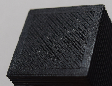
The outline for the cube stuck, but the first pass of diagonal fill did not. The second layer of diagonal fill did, but appeared thin and stringy.
The third layer seemed better and then it started on a honeycomb pattered infill.
Honeycomb infill appeared to be printing fine, and then the inside diagonal fill then again seemed fine.
So, not sure what happened with that first diagonal surface layer... Guess I still have a lot to learn and understand
About 35 minutes to go.
Bleh, I guess not, at about 6mm high, it stopped extruding. I think the filament got snagged... hah!
Edited 1 time(s). Last edit at 01/08/2016 07:56PM by awdorrin.
I am still having issues with the first layer, but I have a 25mm cube printing at the moment.
Nozzle is 0.4mm and Slic3r seems to be starting at 0.40mm, with a 0.2mm layer height configured, which seems high to me.
The outline for the cube stuck, but the first pass of diagonal fill did not. The second layer of diagonal fill did, but appeared thin and stringy.
The third layer seemed better and then it started on a honeycomb pattered infill.
Honeycomb infill appeared to be printing fine, and then the inside diagonal fill then again seemed fine.
So, not sure what happened with that first diagonal surface layer... Guess I still have a lot to learn and understand
About 35 minutes to go.

Bleh, I guess not, at about 6mm high, it stopped extruding. I think the filament got snagged... hah!
Edited 1 time(s). Last edit at 01/08/2016 07:56PM by awdorrin.
|
Re: Prusa I3 confusion January 08, 2016 08:29PM |
Registered: 8 years ago Posts: 26 |
Hmm, same thing happened on my second attempt, at about 7mm high, the PLA stopped extruding...
I can hear the extruder motor spinning, but the filament is not getting pulled in.
After raising the extruder up, I pushed on the filament while pressing the extrude button, and it started working again.
Guess tomorrow I'll be taking the extruder apart to make sure nothing is stuck in there... Not sure what else to check...
|
Re: Prusa I3 confusion January 09, 2016 06:20AM |
Registered: 8 years ago Posts: 8 |
Is your extruder idler tension tight enough?
Here's how I got mine to work a bit better than the standard Slic3r settings:
First layer 0.5mm
Other layers 0.3mm
One layer skirt at 6mm
Filament 1.75mm
Extruder 185/185
Heat bed 60/55
Retraction length 1.5mm
Extra length on restart 0mm (this stopped excess plastic forming on the permiter at the start/stop point)
Still yet to do a full calibration, but pleased so far. Printed a decent whistle off thingiverse (the 118db version 29)
|
Re: Prusa I3 confusion January 09, 2016 11:48AM |
Registered: 8 years ago Posts: 26 |
I am not sure that my extruder has a way to adjust the tension, however that may be the problem.
Once I disassembled the extruder, I found that while pushing/pulling on the filament, that sometimes the filament would turn the stepper motor, but every so often the filament would slip past, without turning the gear, for an inch or so.
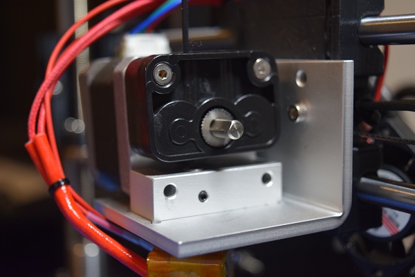
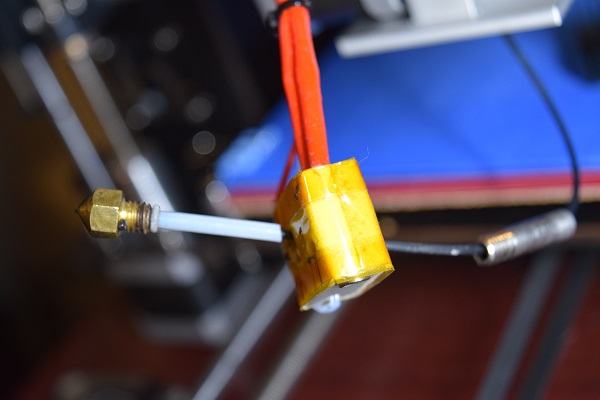
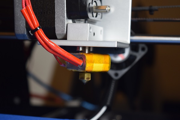
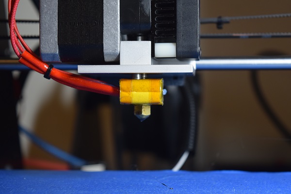
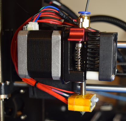
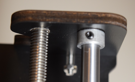
I took a few pictures I took this morning and have attached them to the post.
From what I can tell, there is the toothed gear on the stepper motor, and to the left of that is a, i'll say 'pulley' since I don't know the correct term.
I do not see any way to adjust this, and did not see a way to take the plastic apart, so perhaps there is a spring in there providing tension?
When I reassembled I made sure to tighten both the nozzle and tube to the heatblock (Extruder2.jpg)
I have not yet tried printing after reassembling, but the tension seems like the most likely culprit.
Also, after thinking about the issues with the diagonal fill of the surface layer, I seem to recall the print head moving faster on that, then it was on the border of the shape.
So if the feed rate is an issue, due to slippage, then this could explain everything...
If it is this, then anyone have suggestions on what I need to do with my extruder? New parts?
Thanks!
-Al
|
Re: Prusa I3 confusion January 09, 2016 02:33PM |
Registered: 9 years ago Posts: 1,873 |
It shouldn't be possible to slip filament past the gear by hand. You might want to look at upgrading that with an aluminium set like [www.ebay.ca]
|
Re: Prusa I3 confusion January 09, 2016 02:57PM |
Registered: 8 years ago Posts: 200 |
I had same extruder problem, missing feeds, chugging.
The Replikeo Bowden extruders did not have tensioning like they were selling 1 year ago. This is a major problem. I replaced one of them with a true Bowden tension extruder and I am now making progress in working on the bed issue.
How did you achieve your bed leveling?
The Replikeo Bowden extruders did not have tensioning like they were selling 1 year ago. This is a major problem. I replaced one of them with a true Bowden tension extruder and I am now making progress in working on the bed issue.
How did you achieve your bed leveling?
|
Re: Prusa I3 confusion January 09, 2016 06:05PM |
Registered: 8 years ago Posts: 26 |
Thanks for the link to the tensioning device - looks like I'll be ordering one (will have to see if I can find one closer than China though!)
For leveling the bed, after reading a bunch of different suggestions, I created four macros in Pronterface.
Each macro sends the print head to a different corner of the print bed (about 30mm in from the edges):
I start at FrontLeft, and use that macro, then use the Z-Home button to send the head to the bed.
I slide a strip of printer paper under the head, and adjust that corner's wing nut until I feel a slight drag on the paper.
I then send the print-head to another corner (usually do: FrontLeft, Back Right, Back Left, Front Right, then double check all four corners)
The only issue I've seen with this method is that, if doing this with a cool print head, you need to make sure that there is not a blob of plastic sticking out of the nozzle.
Otherwise the adjustment is off completely.
Maybe there is an easier way to do this, but I'm still learning.
For leveling the bed, after reading a bunch of different suggestions, I created four macros in Pronterface.
Each macro sends the print head to a different corner of the print bed (about 30mm in from the edges):
FrontLeft:  G0 X30 Y30 Z5
FrontRight: G0 X170 Y30 Z5
BackLeft:   G0 X30 Y170 Z5
BackRight:  G0 X170 Y170 Z5
I start at FrontLeft, and use that macro, then use the Z-Home button to send the head to the bed.
I slide a strip of printer paper under the head, and adjust that corner's wing nut until I feel a slight drag on the paper.
I then send the print-head to another corner (usually do: FrontLeft, Back Right, Back Left, Front Right, then double check all four corners)
The only issue I've seen with this method is that, if doing this with a cool print head, you need to make sure that there is not a blob of plastic sticking out of the nozzle.
Otherwise the adjustment is off completely.

Maybe there is an easier way to do this, but I'm still learning.
|
Re: Prusa I3 confusion January 09, 2016 08:05PM |
Registered: 8 years ago Posts: 200 |
|
Re: Prusa I3 confusion January 10, 2016 11:31AM |
Registered: 8 years ago Posts: 26 |
|
Re: Prusa I3 confusion January 15, 2016 12:10AM |
Registered: 8 years ago Posts: 26 |
So my aluminium tension adjustment bracket arrived and I tried assembling this evening.
The new bracket and mount are slightly wider, looks very similar to this: aluminum extruder
Everything seemed to be going well until the M3x40mm screws I used previously to mount everything to the stepper motor turned out to not be long enough.
So, after an unsuccessful search at Home Depot, Lowe's and the local Fastanel, for 45mm or 50mm long screws, back to Amazon I went... 50 M3x50mm screws on the way. Gonna have so many extra parts at this rate.
Guess no playing with the printer this weekend...
|
Re: Prusa I3 confusion January 15, 2016 12:57PM |
Registered: 8 years ago Posts: 200 |
|
Re: Prusa I3 confusion January 22, 2016 06:56PM |
Registered: 8 years ago Posts: 26 |
Unfortunately no Ace Hardware nearby, only some local hardware stores, Home Depot, Lowes, Grainger and few True Value.
True Value actually had a great selection of metric screws, but their M3 lengths stopped at 20mm.
I ended up ordering 50 M3x0.5x50mm screws from Amazon, along with a screw cutter.
Today, after all the parts arrived I was able to assemble and adjust things. Had to reverse the extruder motor and,adjust the Z-endstop.
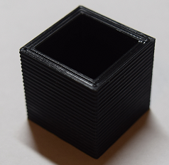
Printing on blue-painters tape, the first print, a 25mm test cube, came out fairly good, I think :-)
Really good adhesion to the blue tape, I had to remove the tape to get the part off!
About the only thing that concerns me is the ridges on the sides of the cube. I'm using a 0.4 nozzle with a 0.2 layer height, so not sure if that is to be expected or not.
Measuring it, it was within 0.1mm of 25mm on each of the axis.
Oh, and with the way my extruder mounts with the new bracket, I'm currently losing 1.5" on the left side of my print bed. So, still some tweaking to do, but now that I can print parts again, that should be fun! :-)
Edited 1 time(s). Last edit at 01/22/2016 06:58PM by awdorrin.
|
Re: Prusa I3 confusion January 22, 2016 07:08PM |
Registered: 9 years ago Posts: 1,873 |
Hey, good to see you printing again  I switched away from the blue tape because I couldn't find the sweet spot between not sticking and sticking like crazy. Elmer's purple is working out a little bit easier for me, although it's better with abs than pla.
Those do look like some pretty big ridges on your Z. I wonder where that's coming from. 0.2mm sounds like a perfectly good layer height, and those ridges look several times bigger than that. What sort of Z screw are you using? There are several different potential causes of Z wobble, including bent Z screws (especially if constrained at both ends) and using layer heights that aren't a multiple of the Z full step.
 I switched away from the blue tape because I couldn't find the sweet spot between not sticking and sticking like crazy. Elmer's purple is working out a little bit easier for me, although it's better with abs than pla.
Those do look like some pretty big ridges on your Z. I wonder where that's coming from. 0.2mm sounds like a perfectly good layer height, and those ridges look several times bigger than that. What sort of Z screw are you using? There are several different potential causes of Z wobble, including bent Z screws (especially if constrained at both ends) and using layer heights that aren't a multiple of the Z full step.
|
Re: Prusa I3 confusion January 23, 2016 11:59AM |
Registered: 8 years ago Posts: 26 |
Well, if I hold the cube against the threads of the Z threaded rod, the ridges appear to fit perfectly, so it looks like it does have something to do with the threaded rod.
I bought this as a kit, so I am not entirely sure about the components, but after measuring:
The smooth rods appear to be M8, measuring 8mm, but the threaded rods seem inconsistent. Neither measure 8mm in diameter, but instead 7.6mm +/- 0.02mm diameter with a 1.25mm pitch. Not quite what I would expect for M8, so I am not sure what they are.
However, the Z rod and nuts do appear fit very well, there is not any noticeable slop in them when I try to wiggle them up/down/around.
The one concern I had during assembly was how the rods attached to the stepper motors with the coupler, it didn't seem like you could ensure that the rods were centered, but I figured that was the reason for having the smooth rods.
While the right-side smooth rod has the collar with set screw, I do not have the same on the left side as the collar's threads were bad, so the set screw would pop out under the slightest of pressure.
The smooth rods appears to be pretty solid, outside of some flex in the top melamine frame, since there is no reinforcing supports for the horizontal plates.
I did some double-checking of the Z-Height on the left and right sides, and it looks like the right hand side was a about 0.24mm higher than the left side.
I am wondering if this could be the cause of the wobble?
Going to relevel the bed and try another cube print.
BTW, thank you for responding to my posts!
|
Re: Prusa I3 confusion January 23, 2016 12:47PM |
Registered: 9 years ago Posts: 1,873 |
My setup is very similar to yours, and I too thought the 8mm smooth rods were good enough, until I put the carriage in the middle of the X axis and tried moving the nozlle up and down. It takes a tiny amount of flex for the carriage to twist around the X axis and make a very noticeable movement of the nozzle. The same degree of flexing in the Z rods can displace the head sideways and produce the artefact you're seeing in your prints. The most likely cause in this case is the threaded rods not being concentric with the motor spindle. Do you happen to own a dial indicator? If so, you could try running it against the threaded rod just above the coupler to confirm if it is running true or not. If it isn't, you could also run against the coupler itself, to see if the problem is at the coupler to motor end or the coupler to threaded rod. If you don't have a dial indicator the best you can do is try and spot any change in position by eye, or feel for tightness by moving the rods by hand with the motors disconnected.
If this is the problem, the bad news is that it's really difficult to fix - it's a weakness in the design taken to save money, but causes a ton of trouble. I copied that design even though I was remaking the Z-axis, and I regret it. I ended up machining the ends of the threaded rods to fit into newly made solid couplers with a constant bore from one end to the other. Other attempts with different sized bores for each end to fit the original threaded rod OD weren't sufficiently concentric.
One thing that can help is to let the top of the threaded rod float freely, but you'd probably want to try that before committing to it, and I don't see a good way of doing that in your machine. One possibility is to drill out the hole at the top to a much bigger size (say 12mm or so), which would let the rod float, and if you didn't like it you could print up a spacer to take up the slack. Ideally, with straight well centered threaded rods, the top should run completely true in the center of the hole. One side of mine is pretty good, the other not so much, and that's after trying really hard! Next time I'm making one piece blocks with mounts for both the smooth and threaded rods at both ends, so that the rods are constrained and parallel before any couplers get involved. It raises the straightness requirements on the threaded rod, but I think I'd prefer to have to shop around for better rods than put up with the wobbles again! Given the size of the wobble on your prints, you may find the top of your rods really thrash around if you float them, which will make it seem like a bad idea. But it's better to be able to see the problem than have it hidden and impacting the print quality. Once you can see the extent to which the rods are off center, it motivates you to find a solution.
(also, the float-the-top idea works better if the problem is bent rods than for non-concentric problems. If it's not concentric the sideways force gets worse towards the bottom, and having the top flop around doesn't help that much)
Edited 3 time(s). Last edit at 01/23/2016 12:53PM by JamesK.
|
Re: Prusa I3 confusion January 23, 2016 01:28PM |
Registered: 8 years ago Posts: 26 |
I printed another 25mm cube, and it looks a little better after the adjustment, but the wobble artifact is still there.
I took more care this time removing the cube, and marked the orientation on the printbed, so I could remember the cube's orientation.
From the looks of it, the wobble is more pronounced on the left hand side of the prints. The right hand side seems fairly smooth, while the left has the noticeable 1.75mm pattern that matches the thread.
I do not have dial indicator, so instead I did an experiment where I brought the print head up to about 150mm and told it to home. I then put my head with my chin on my desk.
Sure enough, I could see a slight wobble on the left-hand Z threaded rod. I could not notice a wobble on the right-hand rod.
Not sure if the left rod is bent, or just not centered in the coupler. I guess I'll have to disassemble to see if I can tell and if it is not bent, then maybe I can try to get it centered a little better.
That is the fun thing about this, learning what is causing things like this and then what to do to fix or work-around the issue.
|
Re: Prusa I3 confusion January 23, 2016 02:14PM |
Registered: 9 years ago Posts: 1,873 |
Quote
That is the fun thing about this, learning what is causing things like this and then what to do to fix or work-around the issue.
Yes, totally agree. Although sometimes the idea of a printer that "just works" also seems quite appealing! It would be nice to have an "old faithful" and a "bleeding edge" pair of printers

|
Re: Prusa I3 confusion January 23, 2016 03:34PM |
Registered: 8 years ago Posts: 26 |
Yeah, an off-the-shelf professionally made printer would be nice, but after seeing the price tag on those, I'm happy with this route :-)
So I removed the left threaded rod and there is a very slight curve in the rod. It looks like maybe 0.1mm off the counter-top at the opposite end.
With the rod being about 12 inches long, to me, it seems within a reasonable tolerance, so not sure if this is part of the cause or not.
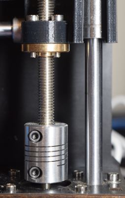
What I realized when reassembling the rod, is that the coupling device on the stepper motor is flexible! It did not occur to me that those spiral cuts were all the way through the coupler. It makes sense that it is intended to compensate for the rod and motor shaft not lining up perfectly.
I was looking back at the parts that hold the nuts to the rods, and it does appear that there is some flexibility in there that is meant to reduce transferring the threaded rod sway to the lift brackets on the smooth rod. So I guess I should be looking at the nozzle, on Z movement, and not really the threaded rods.
So much more to learn! :-)
|
Re: Prusa I3 confusion January 24, 2016 12:05PM |
Registered: 8 years ago Posts: 26 |
James,
After a bit more research, and re-reading your post, I think I understand this more fully.
There was a very good write-up that I found here: Taxonomy of Z axis artifacts in extrusion-based 3d printing
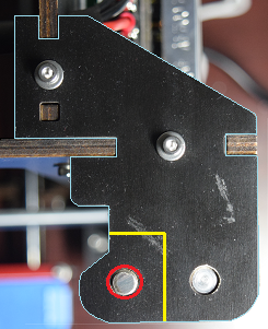
So now I understand what you meannt about letting the Z-threaded rod float. I took a picture of my printer, and did a little editing in paint:
So, I figure I could either drill out the hole for the Z-threaded rod (the red circle) - or, I could cut the entire piece away (yellow lines); Or an even better solution would be if I could find a 3d model for these top-end brackets, modify it, and print some new brackets. I have spent a little time searching on Thingiverse, but have not had any luck finding a model yet.
-Al
|
Re: Prusa I3 confusion January 24, 2016 12:14PM |
Registered: 9 years ago Posts: 1,873 |
|
Re: Prusa I3 confusion January 24, 2016 12:52PM |
Registered: 10 years ago Posts: 477 |
Quote
awdorrin
James,
After a bit more research, and re-reading your post, I think I understand this more fully.
There was a very good write-up that I found here: Taxonomy of Z axis artifacts in extrusion-based 3d printing
So now I understand what you meannt about letting the Z-threaded rod float. I took a picture of my printer, and did a little editing in paint:
[attachment 70683 Z_top_end.png]
So, I figure I could either drill out the hole for the Z-threaded rod (the red circle) - or, I could cut the entire piece away (yellow lines); Or an even better solution would be if I could find a 3d model for these top-end brackets, modify it, and print some new brackets. I have spent a little time searching on Thingiverse, but have not had any luck finding a model yet.
-Al
That is a great article.
You could also just trim a few mm off the Z threaded rods so they sit under the top mount. That way you will have the top mount covering them and things like clothing won't get caught on them.
Steve
|
Re: Prusa I3 confusion January 28, 2016 04:52PM |
Registered: 8 years ago Posts: 26 |
I wanted to take a non-destructive approach to resolving this, so didn't want to cut the rods or the existing brackets.
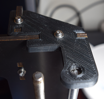
It took me a little while, but I was able to find a template on Thingiverse for a Geeetech Prusa I3 that was very close to the bracket used on my kit.
After some manipulation in Sketchup, I was able to change the model to fit my printer properly, and I printed two usable, altered brackets.
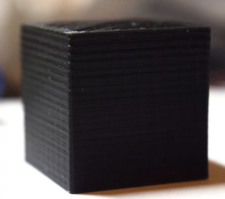
After installing the new brackets, I was able to print the following 25mm test cube:
A very dramatic difference! I is a little odd to see how much the threaded rods wobble without being constrained at the top, but the prints are definitely better than they were previously.
Now I get to move onto some other issues, like surface fill and threads/globs.:-)
|
Re: Prusa I3 confusion January 28, 2016 05:01PM |
Registered: 9 years ago Posts: 1,873 |
Sorry, only registered users may post in this forum.
