Generation 7 Electronics/fr
|
English • العربية • български • català • čeština • Deutsch • Ελληνικά • español • فارسی • français • hrvatski • magyar • italiano • română • 日本語 • 한국어 • lietuvių • Nederlands • norsk • polski • português • русский • Türkçe • українська • 中文(中国大陆) • 中文(台灣) • עברית • azərbaycanca • |
Release status: working
| Description | Generation 7 Electronics
|
| License | various - see individual boards
|
| Author | |
| Contributors | |
| Based-on | [[]]
|
| Categories | |
| CAD Models | |
| External Link | (none)
|
Cette page décrit le fonctionnement des cartes Gen7 pour le pilotage d'une imprimante Reprap. La Gen7 forme un ensemble complet de cartes électroniques conçus pour être réplicable. La réplication est ce qui rend le projet RepRap unique, cela devrait être étendue à l'électronique. Tous les circuits imprimés Gen7 peuvent être fabriqués sur votre Mendel, Prusa Mendel, Huxley, ou sur une machine de fraisage CNC général. L'objectif à long terme est d'imprimer directement les pistes électriques.
La conception électronique de cette carte est très similaire à d'autres solutions , comme RAMPS , Pololu_Electronics ou Sanguinololu . L'électronique de la GEN7 peut piloter exactement le même matériel, en utilisant les mêmes firmwares . De plus, il est livré avec quelques détails supplémentaires pour le rendre plus souple et beaucoup plus fiable.
- Discutez de cette électronique sur le forum GEN7 Electronics .
- Suivre le développement et télécharger dans GEN7 Electronics GitHub repository.
- Si vous voulez juste avoir une vision du produit latest release files.
Contents
Caractéristiques & Spécifications
Points forts
- C'est rapide! la carte fonctionne à 20 MHz -> 25% de vitesse en plus.
- C'est complet! Peut piloter un plan de travail chauffé.
- Il est confortable! Il y a plusieurs connecteurs d'alimentation et s'éteint automatiquement.
- C'est ouvert! Bien adapté pour le développement communautaire et la personnalisation.
- Il est souple! capacité de piloter des moteurs et chauffages avec des tensions différentes .
- C'est abordable! Le circuit imprimé est facile à fabriquer sur une RepRap.
Détails
- Carte simple face.
- Dimensions 100 x 130 mm.
- Processeur: ATmega644, ATmega644P or ATmega1284P (Atmel Corp.)
- pilote de moteurs pas à pas Pololu, interchangeable.
- 4 contrôleurs pour moteurs pas à pas (avec micropas de 1/16).
- Branchement pour un convertisseur USB-to-TTL. À venir : un convertiseeur USB-TTL déjà intégré.
- Intégration complète pour le pilotage de l'extrudeur (moteur, chauffage et thermistance).
- Intégration complète pour le chauffage du plan de travail (heater, thermistor).
- Permet de réutiliser une ancienne ( ou nouvelle) alimentation de PC avec un connecteur de 20 ou 24 broches ATX.
- Alimentation possible depuis un connecteur MOLEX 4 broches.
- Utilisation de connecteurs standard.
- Adaptée aussi bien pour des connecteurs enfichables qu'à vis.
- LEDs pour les fonctions veille, alimentation, chauffage.
- Peut allumer ou éteindre l'alimentation de la carte de façon logicielle à condition que la carte soit alimentée via le connecteur à 20 broches.
- Bouton RESET.
- ICMP header.
Objectifs de la conception
- Gardez la notion de replica. Cela nécessite une distance minimale entre deux pistes de 0,4 mm. Cette règle élimine la plupart du temps tous les composants CMS.
- Obtenir l'indépendante à partir de solutions industrielles.
- Mettre l'accent sur la flexibilité, la facilité d'utilisation et la fiabilité. En conséquence, de nouvelles caractéristiques non essentielles ont une faible priorité.
Composants
Gen7 est une solution avec une carte comprenant quelques composants assurant toutes les fonctions décrites precedemment, on lui associe 3 petites cartes qui supportent les capteurs fins de course optoélectronique:
Carte Principale
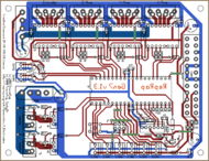
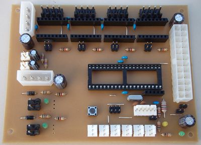
Gen7_Board_1.3.1 correspond à l'unité centrale. Elle peut piloter une machine RepRap à elle seul, mais pas beaucoup plus. Elle fourni sa pleine puissance uniquement pour l'essentiel.
Fins de course
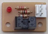
Gen7 Endstop 1.3.1 est une carte qui supporte un fin de course optique, il faut au minimum 3 cartes pour une Reprap et 6 si vous désirez câbler toutes les fins de course maxi et mini.
Revisions
Pour les plus anciennes versions, voir la section #History.
15. May 2012: v1.4
New features:
- Most important: Gen7 features now an extension header, so you can stack a feature-rich board on top of the base board. This shall allow for SD card support, additional extruders, displays and perhaps even multi-color extruders.
- Moved motor heaters from KK156 to KK100 ones. KK156 are Gen3 and screw terminal compatible, KK100 are RAMPS/Sanguinololu/Gen6 compatible. The later are significantly cheaper and a lot more in use these days.
- Reduced the number of endstops to 3, so endstops no longer share pins with the ISP header. Additional endstops can go onto the extension board.
- Connect the thermistor to 5V Standby. This allows to read temperatures without turning the power supply on and requires just 0.1 mA additional juice at room temperature, so the additional energy needed for running the thing 24/7 is neglibile.
- Better GND routing for even more accurate temperature readings.
- Reduce resistors between ATmega and MOSFETs to 10 Ohms to allow for higher PWM frequencies.
- Tested support for the ATmega1284P.
Comment se procurer
Vous pouvez acheter les kits GEN7 auprès de Traumflug, sur le site Paoparts ou sur le site eMotion Tech. Ou bien dedicated page.
Parts Lists
For the parts lists of Gen7 components, see their dedicated page
To assemble or verify parts lists, open the layout with gEDA/PCB and export a "BOM". This will give you a list of all required components.
Divers
Outre les pièces nécessaires pour les composants individuels, vous aurez besoin de fils minces pour cabler les signaux des thermistances et des fins de course. Vous pouvez récupérer les câbles que vous trouverez entre une carte mère PC et les disques durs.
Le Chauffage et l'alimentation des moteurs ont besoin d'un peu plus de courant, le fil doit être épais. C'est une bonne idée d'utiliser des câbles pour appareils ménagers électriques. Ces derniers sont habituellement 2x ou 3x 0,75 mm 2 . Les torsades des fils réduisent l'influence électromagnétique.
Instructions d'assemblage
Si vous avez assemblée et testé la carte controleur et les fins de course , le reste est très simple.
- Avant toute chose une précaution importante : ne jamais débrancher un moteur de la carte polulu, quand le système est sous tension, la carte Polulu ne résiste pas et ...... PLOUFFFFF. ... de manière générale faites obligatoirement les connections et deconnections alim arrêté.
- Les potentiomètre sur le Pololus devrait toujours être réglé. Cela permet de régler le courant maximal qui passe dans les moteurs. pas assez de courant et le moteur perd des pas, trop de courant et le moteur surchauffe.
- Tourner le potar tout à la gauche. Puis tournez à droite par petites étapes. Après chaque étape si le moteur a suffisamment de couple, il doit se déplacer sur tout le chemin de haut en bas. puis recommencer en tournant d' 1 / 8 de tour à la droite.
Notice Regarding Legal Stuff
Generation 7 Electronics isn't a device in the sense of European Community regulation 2004/108/EG (EMC Directive). The reasons include:
- Gen7 doesn't include a power supply, so a Gen7 can't be used on it's own.
- Same for the stepper drivers. No stepper drivers, no useable Gen7.
- Heaters, thermistors, dito.
- The instructions seen on the Gen7 wiki pages give you hints on how to build your own device, they're not to be seen as installation instructions or a manual of a finished device.
If you use a Gen7 to assemble something usable, check (at least) the following if you want to conform to said regulation:
- Is there a metal housing? A Faraday Cage solves most electromagnetic issues.
- Connected cables can also be subject to electromagnetic stuff. Shielding them helps.
- Is there a manual and are there installation instructions conforming to the regulation?
If you buy and assemble an Generation 7 Electronics kit, you're manufacturer in the sense of the EMC Directive, not an end user. As long as you're developing and testing, most EMC regulations don't apply (for obvious reasons). The directive just wants you to protect devices of third parties from yours, so don't run a Gen7 right next to your neighbour's cardiac pacemaker. There's no time limit for developing and testing.
That said, this section mostly applies to all currently known RepRap electronics. Also, the said was written after investigation of relevant law texts by an mechanical engineer, not a lawyer.
Relevant law: EMVG, implementing the EC directive for Germany.
Development
Current status of development can be found at the Generation 7 Electronics GitHub repository. The short term goals are listed above in the #Releases section.
Layout, PCB Editing
Gen7 uses gEDA, a true open source set of Electronics Development Applications (EDA). While gEDA has a bit of a learning curve and has some room for improvement regarding the graphical user interface, it's reliable, fast and well suited for the task. gEDA is available for Linux and Mac OS X and has ready-to-use packages on Debian/Ubuntu and SuSe. To install it on Ubuntu, simply type
sudo apt-get install geda geda-utils geda-xgsch2pcb
and you'll find schematics and PCB layout editor applications in your applications menu.
Additionally, you want to download the design files with Git or GitHub's download button. In the later case choose to download source and unpack that when done.
Typical Work Loop with gEDA
Here you have a typical work loop for changing these electronics with the gEDA/PCB tool chain:
- Always start editing with the project (.gsch2pcb suffix) file. You can open it by double-clicking it.
- Select the schematics and use the button below the list to open it.
- When done, save it and return to the project.
- Open the PCB using one of the buttons to the right. Both have almost the same functionality.
- If you have chosen to update the PCB, footprints no longer in use will have vanished and new or previously missing ones appear in the upper left corner. An updated list of connections (netlist) will have been loaded. Update the rats nest to find areas requiring work.
- When done, save it and return to the project.
You get the idea?
Bug Fixing, Sending Changes
This is community development, so getting changes from everyone is more than welcome. Write them to the forum, to the reprap-dev mailing list, use GitHub's Issue Tracker, whatever is most convenient for you. If you fork the repository at GitHub, you can also send Traumflug pull requests.
PCB Manufacturing
gEDA can export PCBs to the Gerber and other file formats, of course.
Milling
On how to proceed further with that, see the PCB Milling page.
Etching
For etching, you likely want to reduce the amount of etched copper to a minimum. One way to get there perfectly, is to lay a ground plane into the layout.
Note: if you're in a hurry, you can leave out the step removing the tracks on the "GND-sldr" layer and setting Thermals. It'll work anyway.
- Open the layout in PCB.
- Switch to the "GND-sldr" layer.
- Remove all tracks on this layer ( = all light blue ones = all of the GND net minus vias and bridges, find the net with Menu -> Window -> Netlist).
- Draw a RECT (find the tool in the left bar) as big as the entire board.
- Do an "optimize rats nest" (o-key).
- Some non-GND tracks might be shortened with the new ground plane. Move the mouse over each of these tracks and press the "j" key (on your keyboard). Works for tracks hidden behind the ground plane as well, you'll see the difference immediately.
- For pins and pads you actually want to connect to the ground plane, set a Thermal (THRM tool to the left).
- Loop the last three steps until you get congratulations (no errors) on "optimize rats nest".
- In case the default clearance between the copper plane and pins/tracks are not sufficient for your purposes, you can adjust them with some command line work:
- Switch to the "solder" layer.
- Select Menu -> Edit -> Select all visible.
- Select Menu -> Windows -> Command Entry.
- Type the following and hit Enter:
ChangeClearSize(selectedlines, 0.5, mm)
- Repeat the above with
selectedpinsinstead ofselectedlines. - Repeat both of the above on the "Vcc-sldr" layer.
- As you probably guessed already, you can change this "0.5" to arbitrary values and "mm" to "mil", and use different values for each of the 4 groups.
- You're done.
On how to proceed with this etching-optimized board, see ... [Links needed]
Etching via Toner Transfer
Additionally to the above, the layout can be optimized for the toner transfer method even more:
- I'm not a real pro at toner transfer etching, so I generally oversize the traces and undersize the holes in the pads. This makes it more likely to get a good board. Toner transfer can be a bit of a pain. It is kitchen science in every way. Plus, since you are often drilling pads by hand it helps to oversize the pads too. Wider traces and smaller holes help the most. The wider traces help avoid open traces when etching is finished, and undersized holes helps avoid pads that etch too thin and are then liable to pop off the board when soldering. Also a smaller hole helps center the drill bit better.
Following up on this statement, the minimum track width was raised from 20 mil to 30 mil. As the minimum gap between copper is still 16 mil, other manufacturing processes shouldn't suffer from this. --Traumflug 20:33, 8 June 2011 (UTC)
You can reduce drill sizes with a few quick commands:
- Open the layout in PCB.
- Drag a rectangle over the entire board to select all elements.
- Select Menu -> Window -> Command Entry.
- Type the following two commands:
changedrillsize(selectedpins, 0.5, mm)
changedrillsize(selectedvias, 0.5, mm)
Voilá, all drills are reduced to 0.5 mm, just right to be a center hole for manual drilling.
Practical tips for toner transfer see DIY PCBs double sided toner transfer.
History
(Well, that part of the history which didn't result in a Release).
The Forum thread (german), where everything started.
16. August 2011: 1.3.1
Version de correction de bug.
- Attempt to prevent bootloader corruption by turning on the Brown Out Detector.
- Make the bootloader it's self a bit shorter.
- pas de changement de hardware.
22. July 2011: 1.3
Nouvelles fonctionalités:
- Supported EDA toolchain is now gEDA 20100929, the one coming with Ubuntu 11.04.
- Use stronger 2 pin, 4 mm connectors (same type as the motors) for the heaters. These match the required current much better.
- Suppression du Mosfet pour le ventilateur. Peut d'utilisateur utilisait le ventilateur. Si vous etes un de ceux la, connectez direcement le ventilateur sur l'alimentation.
- suppression du connecteur I2C . qui n'était pas utilisé
- Mise en place d'un connecteur 2 broches. la broche supplémentaire causiat beuacoup de confusion.
- Remplacement du connecteur ATX20 par une ATX24 ATX24. Le nouveau connecteur est compatible avec les nouvelles alimentation et accept les connection avec une connecteur ATX20.
- Use another disk power type connector to supply the heaters. This allows to run a heated bed directly off the Gen7 board, without relays in between. This also introduces the ability to use different voltages for motors and heaters, without making things more complex for casual users.
- les MOSFETs sont maintenant verticales, pour un meilleur refroidissement et la mise en place d'un radiateur.
Work Around Christmas 2010
Mostly done by Jacky2k.
24.12.2010: A first version of the Gen7 board has been etched and is being tested. The hardware seems to work, but the software still needs to be ported and tested with a RepRap.
29.12.2010: Some patches were made in the firmware to support endstops and homing. The patched firmware can be downloaded in the firmware section.
30.12.2010: Some more patches to the firmware. Current firmware seems to be stable and working. Not 100% tested yet.
04.01.2011: We found some bugs in the firmware again. All of them seems to be fixed, release is planned tomorrow.
05.01.2011: Uploaded current firmware with a lot of patches.
08.01.2011: Some little modifications of the PCB are required. Pull-up resistors for I²C are missing, we want to change some headers to more common one, some resistor values are missing, ...
09.02.2011: The master branch of FiveD on Arduino firmware is ported and seems to work but is not tested 100%. The config file for the firmware will come soon.
March 2011: Four Mendels are driven by Gen7 Electronics successfully, first reprap'd PCBs were shipped.


