David's Hotend (Bowden and Direct)
|
English • العربية • български • català • čeština • Deutsch • Ελληνικά • español • فارسی • français • hrvatski • magyar • italiano • română • 日本語 • 한국어 • lietuvių • Nederlands • norsk • polski • português • русский • Türkçe • українська • 中文(中国大陆) • 中文(台灣) • עברית • azərbaycanca • |
Mechanical: Overview | Mendel solid model files | Procurement | Preparation of materials | Assembly notes | Extruder | X-axis | Z-axis | Y-axis | Circuit boards | Frame | Squaring the axes
Release status: Working
| Description | Dual-purpose Bowden or Direct Drive Extruder Hot-End
|
| License | GPL
|
| Author | |
| Contributors | |
| Based-on | |
| Categories | |
| CAD Models | not available
|
| External Link |
Contents
Features
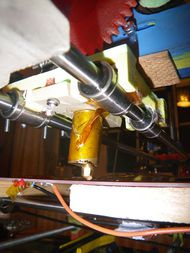
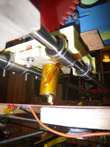
A dual-purpose hot-end which can be used in either Bowden or direct drive extruder, using a Wades extruder to drive either mode.
Advantages
- Removable nozzle - so extruded filament diameter can be varied in seconds, and cleaning is easy
- Suitable for Bowden and Direct Drive setup without modification
- Approx 2mins to switch between either Bowden or direct setups
- Lathe not required
Disadvantages
- Requires more tools/stages than the later versions of the geared extruder
Time Required
3 hours (2 to make holder, 1 for 2 nozzles)
Bill of Materials
Brass rod: 16mm diam (for heater block; if buying I'd get copper or aluminium as better heat conductor)
Brass rod: 6mm diam (for nipple; ditto re copper)
  or M6 Grease Nipple (but I found trying to braze the tip closed then redrilling to smalled diameter was more hassle than making from scratch)
  or gas nipple, but couldn't find where to buy them
Wire wound resistor (3W)
Thermistor (100k)
PEEK block 50x20x5mm. I cut it from a bit of round cast-off I got off ebay.
PTFE Tube (6.4mm OD x 3.2mm ID)
Block of wood to make a jig for sanding various faces on things (I used 5x5cm, but any similar scrap off the woodpile would do)
Thermal paste or fire cement (see below re this)
Kapton tape (for electrical and some thermal insulation)
4x M3 screw 15mm
2x M3 nut
6x M3 washer (optional)
Tools Required
Drill press,
Drill clamp
Drill bits: 2.5mm, 3.2mm, 5mm, 6mm  [16mm drill for jig)
Tap: M6 (ideally x3 - taper, 2nd and bottom to thread right to the bottom of the hole)
     M3 (taper only OK)
Dremel-type metal cutting wheel (mounted in drill press)
Dremel or hacksaw
Vernier caliper or similar accurate measuring device
Optional
  Collet to fit 6mm rod
  Bench mounted belt sander with 80 grit belt (else use drill and (file or dremel))
Making the Heating block
Level the table of the drill press, so it is exactly 90degrees to the axis of the chuck
Cut your 16mm rod to length (I happened to have a chunk 27mm, but if not I'd probably aim for 25mm)
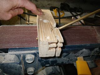
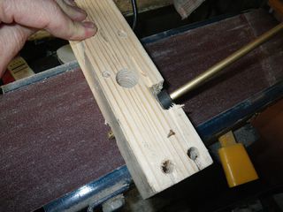
Drill 16mm hole vertically in scrap wood. This will be used to hold heater block perpendicular to the sander to tidy the faces.
Sand the ends flat on the bench sander (by dropping down the hole in the block
Clamp the heater block in the vice with one of the new faces upward
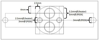
Mark 4mm in from each side on a line passing through the centre of the circular face
For the filament hole: From one mark drill 3.2mm hole through the entire block out the other end. make sure to regularly clear the hole and drill slowly to keep it perfectly vertical (I rotated my heater block in the vice, I'm not sure thats essential but I was trying to compensate for a slightly bent drill)
From each end: drill this hole out to 5mm (5-6mm deep at one end, 10mm deep the other, leaving a 10mm section joining the two holes which is still 3.2mm diameter). The 10mm hole may be unnecessary if you never plan on using a Bowden rod (which will thread into it), but you may need to take care with the seal between the PEEK and the block to avoid melted plastic oozing out, and perhaps use a slightly thicker PEEK block for same reason. Feel free to edit this if you test it out as I didn't...
Tap these two 5mm holes out to M6 (I unplug my drill press and hold the taps in the chuck, and turn the spindle by hand)
For Heating Resistor: From the other mark (4mm from side as above) drill a hole that will just allow the heating resistor to fit inside (5mm with my resistor). I slightly overdrilled the hole to bring the lead back inside, but I'm sacrificing close contact and therefore heat transfer. [With silicon grease as thermal paste and a 3W wirewound resistor, heating is still under 5 mins to 230deg. Alternatively your could drill until you just break through the other end to allow the lead to pass out of the block. If using firecement/adhesive this would probably be more efficient, though not so tidy with wires
For Thermistor: Drill a hole to fit your thermistor from the side of the block at a point close to the nozzle, and away from the heating resistor. I did mine at about 45deg to ensure the silicon grease stayed in, but you could either drill it directly from the side (to reduce the block to conduction), or drill vertically from the same face as the heater to have tidier wires
For attachment to PEEK block: 2.5mm in from edges, Drill 2.5mm holes 10mm deep at the points of the cross 90deg to the heater/filament line and tap them out to M3.
Optional Insulation: Now wrap Kapton tape around the heater block. If you put multiple layers like corrigated cardboard around the block, air gaps will be formed which help insulate it and reduce air loss. Little cylinders around a toothpick stuck vertially around the block make good spacers, and can then be covered with another layer of Kapton) . This also helps to stop it cooling so much if you have a fan
The heating block is now done! See below for some comments regarding thermal paste and the thermistor/resistor electrical insulation
Making the Nozzle
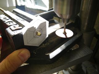
Print and cut out the hex pattern, including the 6mm hole at the centre.
Level Drill Table (if not done above)
Drill 6mm hole vertically in your wooden jig (for facing ends). Drill another one at 45degrees (for the taper) This should ideally go corner to corner to ensure the collet has a stable support when rotating the rod.
I would suggest doing each stage following to both ends of the rod simultaneously so you will end up with two nozzles without having to change tools too often.
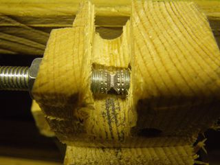
Dropping the rod down the hold in your jig onto the belt sander face, sand the ends of the 6mm rod to ensure flat face at the centre as per heater block (only the centre has to be flat as the edges are about to be removed)
Lock the collet onto the rod. With my jig, it's 53mm to get the taper nearly to the centre of the rod - experiment to get it correct with your setup.
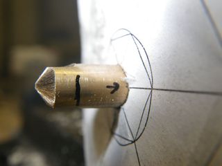
Placing the rod in the 45deg hole rotate it on the sander until the collet sits flat against the jig. This will get you a nice conical taper. DON'T taper right to the centre - leave about 1-2mm flat. (this will depend on the angle of your 3.2mm drill bit tip, how long you want the length of the narrow hole in your nozzle, how much you worry about the nozzle catching on the print vs pressing layers together, and how worried you are about botching it and drilling crooked/through the taper from the other end. As a rule of thumb I aim for roughly 3x the diameter of the intended hole (eg 0.5 -> 1.5mm diameter face.)
Place the rod horizontal in the drill vice. Glue/tape the hex pattern on the end face of your drill vice centred on the rod
Change the drill speed to max (don't forget to unplug it if you're handling the spindle)
Put a dremel cutting disk in the drill and align the height correctly to take 0.5mm off the top of the rod. Ideally use a slightly heavier duty grinding wheel as it will ride up less and your faces will be flatter. If you're not quite sure of the height, aim to take off a little less to give you room for correction
With a fine permanent marker or scribe, put a small dot on the rod approx 10mm from the end and mark a line around the rod 3mm from the edge of the taper
Align the dot with one of the hex lines
Don't forget to put on your goggles now, very fine particles are generated and you eye will probably be about the right location to catch them (whereever it is)
Sliding the drill vice gently under the cutting disk start cutting a face into the rod (do I have to mention turning the drill on?).
Check the amount removed with your vernier calipers or a 5.5mm spanner. If you've got it a little wrong realign the cutting disk (you're doing a number of faces, so it's probably worth it). Otherwise you could just gently lower the drill chuck to cut a bit more.
Check the face is square. If not your rod isn't held horizontal, your table isn't at 90deg to your drilling axis, or the cutting disk rode up on the face (in which case go a bit slower and hold it still when the face is 'finished' to allow it to correct the cut.
Rotate by 60deg (by aligning the dot on the next line)
Repeat for all 6 faces (checking the latter 3 with a 5mm spanner). Then swap ends and do the other 6 faces for your second nozzle.
Now cut off the nozzle ends with a dremel or hacksaw at about 11mm (plus a bit to allow facing the cut surface back flat.)
Face off the cut surface of the nozzles with the sander same as above, then clean the edges gently by rotating on the belt, or with a file.
Measure the nozzle length with vernier caliper and write the number down.
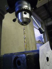
Clamp the nozzle in the drill with tip up inside the chuck and clamp the 3.2mm drill vertically in the drill vice. Align it directly under the nozzle face and check the height of your drill when just pushed against the face. Now figure out exactly how much you need to drill out. This will be the length of the nozzle measured above subtracting the length you want your fine nozzle hole to be (I chose 0.5mm).
Unplugging first, adjust your spindle to slow the drill down to the slowest speed (approx 600rpm on mine)
Close your spindle cover and plug the drill back in again.
Recheck your calculations for drilling distance. *This is critical, drilling too far here will ruin all your work!!*
Now start to drill by lowering the piece onto the drill bit. Check it is aligned centrally (the drill bit shouldn't be wobbling if it is dead centre)
Drill out in small amounts, clearing the bit regularly and spraying cutting fluid into the hole being drilled. I use WD40 for this which works OK with brass etc.
Once your hole is drilled to the correct depth, remove the piece and check you've got it right (ie not too shallow, and not so deep you've drilled out through the taper.
You may be willing to drill the fine nozzle hole at this stage. I delayed it, as I wasn't sure it might not be slightly crushed by clamping during the threading step, though given compliance of brass and distance from the clamping face this seems retrospectively relatively unlikely.
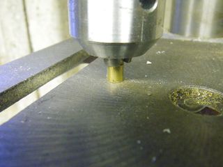
Clean any swarf away and sit the nozzle on the press table, tip pointing upward (this is to ensure its will be in the chuck vertically). Centre it under the chuck and clamp it with the chuck by the recently cut faces in chuck .
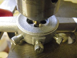
Drop the table enough to allow the die to be positioned under it. Place your M6 die on the press table so it is flat, but held so it won't rotate.
Unplug your drill press, and open the top to expose the spindle head so you can turn it by hand. If you don't mind the risk of losing your fingers if the drill accidentally starts you can leave it plugged in - I quite like mine attached and I already have an uncle and a grandfather with "micro-digitorum" secondary to power tool exposure, so choose to invest the extra few seconds. Much less time than brushing your teeth and you do that don't you!
Gently lowering the nozzle onto the die simultaneously rotate the spinde to cut the M6 thread up to the point you have cut the flats. If your die is tapered on one side make sure you start cutting with this face, but you may want to reverse it for a final cut
Clamp your fine nozzle drill in your drill vice so it is pointing vertically. These bits are quite fragile, so be careful here. Align it directly under the centre of the nozzle held in the drill press, and gently and slowly drill out the nozzle hole by lowering the nozzle onto the drill bit. It will self align into the cone left by the 3.2mm drill bit.
Check the hole by eye and if it the hole is messy then gently hand twist a slightly larger bit to clean it off.
The nozzle is now done!
Making the PEEK insulator
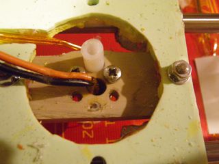
As noted above I used a 55x20x5mm block of PEEK. Holes were drilled centrally in alignment with the heater block, and at the ends to allow M3 screws to hold it onto the X carriage.
After some testing I found the PTFE liner swelled in the gap between the PEEK and the extruder (ie a 5mm gap the thickness of the carriage base) with high extrusion pressures. I thus cut and drilled another sleeve of PEEK to surround this and eliminate swelling.
The M3 bolts I had were too long, so I cut them with bolt cutters and cleaned the ends with the sander.
Nothing particularly complex about this stage...
Thermal Paste and Thermistor/Resistor Mounting
In initial testing instead of fire cement, I used silicon grease mixed with some brass swarf from construction to improve heat conduction from resistor and to thermistor (it's teardrop shape means contact with the wall is poor, and I didn't want to cement things in during testing). With this my hotend got from 25->260degC in approx 5mins. With less than 100 heatings, the grease in contact with the heating resistor turned more like moist grit, and the resistor shell cracked implying overheat (but still worked OK). However the grease surrounding the thermistor remained fine...
Ultimately I used thermal cement to improve heat condution (bad as it is, it's still better than air).
One other thing I did was wrap the wires from thermistor and resistor with kapton tape. However I should have done this even further clear of the block - wire insulation melted and exposed the core even 10mm away from the thermistor, which was the edge of my kapton.
Heat Conduction Values for reference
Fire cement and Silicon (even as grease) are poor conductors (<1w/(m.K))
copper = 400
aluminium = 250
brass = 110
(steel = 45, iron = 80, glass = 1, air = 0.024)
