FoldaRap
|
English • العربية • български • català • čeština • Deutsch • Ελληνικά • español • فارسی • français • hrvatski • magyar • italiano • română • 日本語 • 한국어 • lietuvių • Nederlands • norsk • polski • português • русский • Türkçe • українська • 中文(中国大陆) • 中文(台灣) • עברית • azərbaycanca • |
Release status: working

| Description | first folding reprap
|
| License | |
| Author | |
| Contributors | |
| Based-on | |
| Categories | |
| CAD Models | |
| External Link |
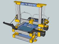
In my obsession dreaming of a folding RepRap, I finally started to make one (end of 2011), after 5-7 months of development, since 2012, I'm able to travel with it around the town/country/world :) (adventures pictured on flickr / youtube). A few thousands were made, from kits or by self-sourcing : FoldaRap_Hall-of-Builds / google-maps.

Contents
Specifications
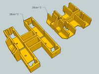
- Printed Parts: 47
- Non-Printed Parts: 266
- Material Cost: around 400-500g
- Cost: 300-600 €
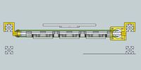
- Printing Size: 140x140x140 mm (or 5.5"x5.5"x5.5")
- Resolution : XYZ = 0.0065 mm (depends of your stepper drivers and the micro-stepping, e.g.: 1.8° motors + 1/32 microstepping = 152-153 step/mm for the rack version)
- Tolerance : 40mm = 40mm +/- 0.05 mm
- Speed: 75-500 mm/s (print-travel, max speed tested yet, 40mm/s for nice corners)
- Accuracy : 0.05mm (50 microns is the lowest layer height tested yet)
- Volumetric speed : 0,4mm = 4mm3/s ; 0,5mm = 8mm3/s ; 0,8mm = 10-12mm3/s (usually)
Special Features
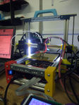
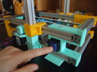
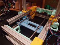
- Foldable !
- Based on standard parts, easy to reuse/recycle
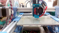
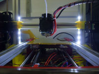
- 1.75mm Direct Driven Bowden Extruder ; fixed on the x-axis for less hysteresis and higher z-print
- Low energy consumption (40-110W)
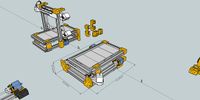
- Minimal footprint : 21 x 35 cm
- Total volume : 34 x 35 x 36 cm / Folded : about 34 x 50 x 10 cm / 3-4kg
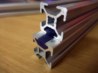
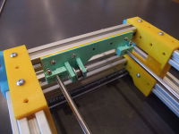
- Printed sliders (PLA) on anodized aluminium extrusion
Community
R&D
FoldaRap x.x
- rubber wheel on alu and encoders ? (idea suggested by Xevel years ago)
- 140x140x140mm and 200x200x200mm version
- rack on the Y-axis (to remove the last belt/pulley)
FoldaRap 4.0
replace the last nema14 by a nema17 (for uniformization purpose)
(or internal power supply)
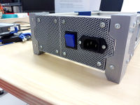
external power supply + plate in front + LCD screen
even more comfortable : use a controller with wifi capabilities like the Duet


FoldaRap 3.5

nema17 in X (even a quite flat one), and a second play compensation is added above

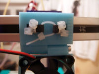
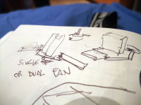
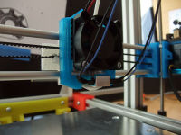
improved print cooling : replacing the blower by two 30mm fans (to have a more even and powerful part cooling). By removing the blower we could attach a flat motor (22mm) under the x-carriage instead of above (just a possibility, putting it above and having more clearance is better).
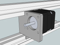
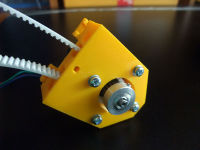
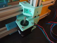
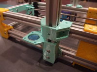
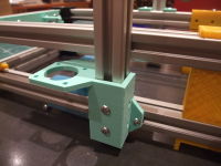
stiffer Y-motor, with two mounting points instead of one

adding some panels to enclose the base frame

new color scheme (silver/navy/orange)


- below 15°C the sliders seems to require a little more force to move (another reason for replacing all the nema14s)
FoldaRap 3.0
Combining old and new ideas, plus the little changes in every parts, and that is good for a new release :)

belt/rack-driven Z-axis, allowing a "Z homing" by gravity = no endstop nor probe are necessary (mechanical simplicity win), even after repeated folding/travel/unfolding/print
quick folding/unfolding, from 5min to 5sec (forum thread)

printed sliders also for the Y-axis (forum thread)
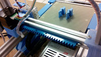
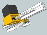
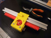
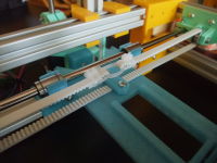
bringing back the rack & pinion (you have the choice belt or rack, but the rack don't need to be tensioned)
e3D-lite6 as a base hotend choice (for easier replication)


FoldaRap 2.5
Changes from the 2.1 :
- nema 17 for the extrusion (instead of a nema 14)
- small blower to cool the plastic (instead of a 40mm axial fan)

updating the wiki...
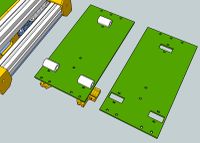
new plates arrangement for the v2.5, to ease color associations ;)


FoldaRap 2.1
Want to try the conveyor idea from the 1X2
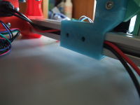
a small notch could retain the wires in place along the z-motor
adding a line to help unfolding the frame at right angle
Back to belt for the moment, but we add this idea to have a constant pressure between rack/pinion
chamfering the base of most of the parts, make them easier to remove and compensate for the usual first layer being often too much squashed
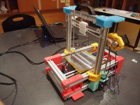
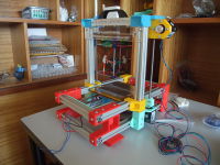
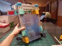
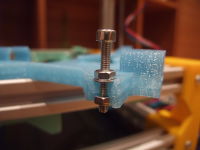
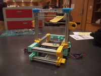
shiny prototype !
designing a new heatsink
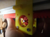
adding holes to allow access to the motor bolts even while the carriage is on the profile and the rack is in place (i.e. : you can remove the motor at any time)
video [6]
adjustable play compensation
first prototype, soon implemented to test, looks promising :)
new front feet, same function but 30% lighter !
a nice hazard with the rumba, the SD card is just where it needs to be ^^ (playing with the lcd is fun too)
yet another try at simplifying the extruder
a possibility for holding two extruders :)
reused the 054 as the second prototype of v1.2
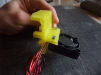
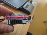
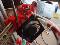
it works nice (no screw holding the fan, it is just clipped) and can be folded
finishing the active cooling addon
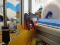
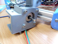
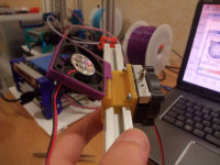
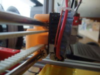
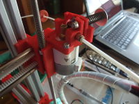
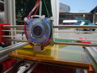
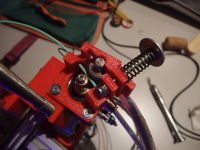
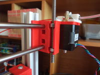
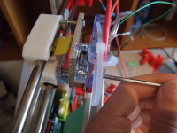
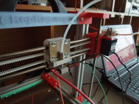
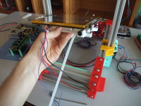
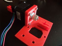
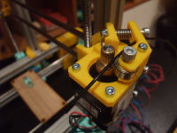
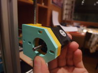
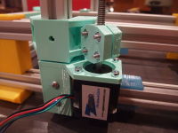
detail of the x-motor
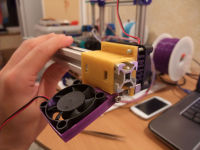
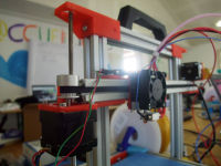
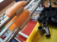
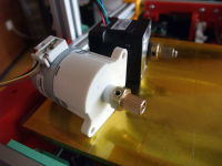
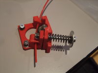
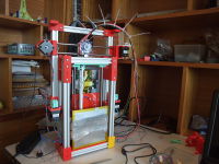
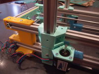
view from the spool side
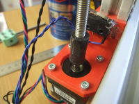
with a minitronics (taken from the mendel-foldarap prototype)
the 1.2 is stightly bigger, few mm
first prototype
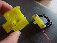
fan holder for the 1.2 x-carriage
v1.2 in progress (easier, cheaper, 160mm x-travel)
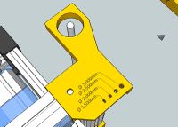
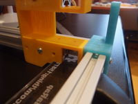
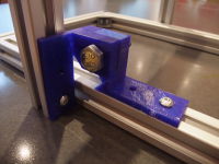
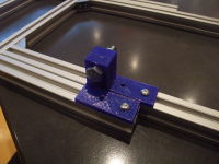
after several tries and suggestions with Xav83, I ended with this simple piece that hold an endstop with a zip-tie :) (for the Z-endstop, or any machine using 20x20 extrusions)


FoldaRap 1.0
a nice suggestion by Adel for this idea of storing tools :) Category:FoldaRap_Development#Store_basic_tools_in_the_frame
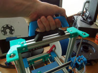
finally found a good model for a printed handle !
back on the print cooling feature [14]
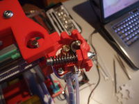
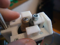
finally added a second spring to the extruder-idler
will try also to use a PMMA bed + blue tape
wanted to try using a Melzi instead of the AzteegX1 (as it's out of stock)
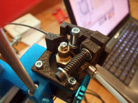
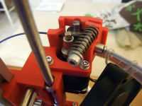
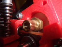
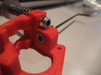
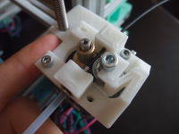
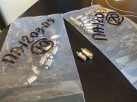
latest version of the extruder idler, with the maritime-models brass insert, a 603zz bearing and a spring found on Radiospare (I updated the wiki's bom), for a simpler to source extruder :) (video [17])
passive cooling anyone ? :) forum
inspired by nathan7's plate[18], works great on the huxley too [19]
in addition to the printed y-carriage, a version for lasercutting (compatible with both lm6uu and printed sliders)
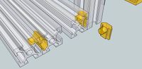
generalized the simplified T-shape to be compatible with extrusions of different thickness (like 1,5mm for KJN and 2mm for Misumi) [20]
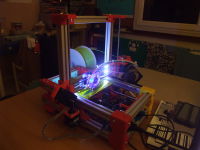
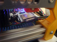
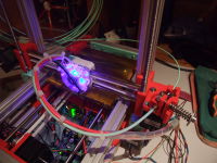
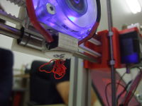
adding some leds :) [21]
Y-sliders (see this thread [22])
micro-hinge
back to direct drive nema 14, and it feels good [23]
New x-ends to be used with M5 rods/nut
a new idea for the hinge : a small insert
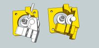
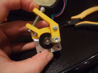
The extruder idler is now an independent sub-assembly, allowing an easier mount/unmount (for transport or eventual quick exchange)
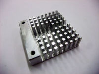
had some time to cut/tap a custom heatsink block for a futur dual hotend :)
an idea to store some tools in the foot (little hex keys clipped on)
back printing :)
most compact hotend evar ?
from the previous researches and a heat-failure this summer, I finally adopted the use of a heatsink instead of a simple alu plate (see also this thread for more informations)
replace the lm6uu by Igus RJMP-01-06 on the XY, enjoy the (almost) silence. video
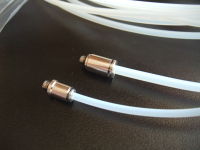
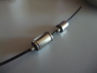
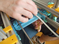
replaced the printed coupling by a small vinyl tube, saving 8 bolts, 8 nuts, 8 washers, and 2 printed parts (or 4 if you count both halves) !
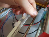
I just had this idea 5 min ago : zip-tie belt clamp for the x-carriage (more to read on the forum).
as I could print at 60mm/s recently (with real long path of filament to reach the full acceleration) or manual extrude at 420mm/min in pronterface, it seems that the more I use the brass insert, the more its grip on the filament is improving : when looking closer there is now a little groove made by the filament pressure ! So, maybe these cheap part just need a little filling to make that groove from the start :)
pursuing the idea for a dual bowden in the same x-carriage :)
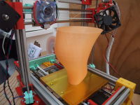
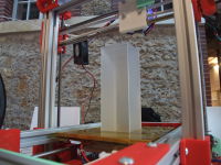
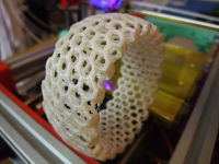
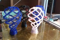
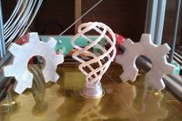
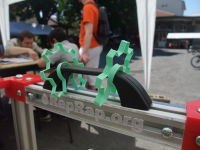
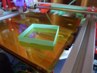
the tornado (thing:7519) scaled to fit 141mm, printed at 40mm/s (can probably go faster now), took 1h30min, good to show the max build volume :)
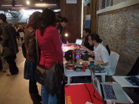
Nice day : I could show the Foldarap to more people and the crowdfunding reached 100% !
it still feel so good to travel with it ^^

(cover for the soon to be published crowdfunding campaign and any purposes it can serve) Next news will be posted on the forum instead of the page (which is getting long), but for a last one : the 4th field test at Hack-In-Paris (at Disney, lol) was very positive, lots of good feedback (maybe a little overwhelming among the hundreds of visitors); I could reach 40mm/s even if still with my rounded-teeth-drive-gear (oiling the rubber roller shaft helped) :)
uploaded the version of the x-carriage I was preparing, optional zip-tie can be added to keep the linear bearing in place (especially the top one, which required me to add a piece of paper on the Huxley)

up to travel again ; now confident to make more prototypes ^^
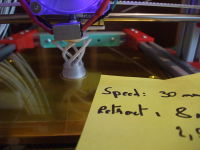
test print showing a z-height of 135mm (of the 145mm that it can reach), printed at 35mm/s still with the brass-drive from maritime-models, but I added a little bit of oil on the rubber roller axis and seems to help
3rd field test : even better flickr
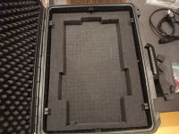
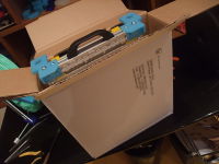
inside the case, to remember how many foam to remove
quick test with a mini-hyena -> need to redesign the idler, with a standard bearing this time (and now with two springs but still lack a support bearing, to match the recent extruders made for pg35l motors)
ready for a 3rd field test ^^ (during Futur en Seine in Paris)
and with the flightcase it's very comfortable to throw the printer at the rear of a car without worrying about it. Field test 2 conclusion : good ^^. Just need to see if the mini-hyena will stop the extruder to slip on the filament (without too much pressure).
still tied to low-speed, but the prints are quite good (I also took the opportunity to finally make a profile for Slic3r)
second practical test during one week seminar, all pics/vids on flickr
last week print, now with the latest Marlin-RC2, without retract and only at 20mm/s (the brass drive gear have somewhat rounded theet... can't wait to try with a mini-hyena). More detailed pics on flickr.

The .ods (open-office) BOM is a little more complete now, and I regrouped the items by suppliers. As I said on the IRC, gasp! If i'm right in my calculation I spent roughly 350€ for my Foldarap but add 200€ of shipping and taxes... next time I'll try to reduce the number of suppliers or source more locally ^^'
(my phone take crapy pics compared to my camera, just wanted to have a good pic this time)

ready to go for the 2nd field test during the coming week ^^ (a seminar of creativity for phd-student, I'll present the fablab concept to them)
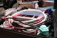
why put such a robust machine in a case ? because you don't have only the machine to carry :) (the FoldaRap2 will be designed around a case structure to push the fusion between the both)
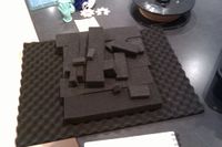
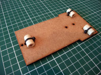
removing precut foam from the supplied pads
the fan was only 1mm too thick to prevent a full sliding (will be resolved with a thinner alu plate), but gently pushing made it work
reversed the spring position to allow to push on it when want to release the filament, but mostly to save space (to put the machine in it's case)
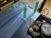
as higly suggested on the IRC during a discussion about these geared stepper, I finally put a fan to cool the motor (only a 60x60 was laying around), even if as per Kliment I lowered the pololu to 0.8A (or 0,32Vref)
curiously I had only one string with the Foldarap while the previous tries on the Huxley where not so successful (but blue/black prints are months old and the Huxley was not so well calibrated as today)
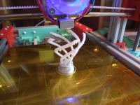
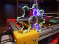
I started by some more oshw logo's before remembering the light-bulb should make a good test for retraction (in case that can play, it was a sample of faberdashery pearly-white)
only one-two little strings, almost not noticeable :)
I never used a stepper with a gearbox, the retract seems sloooow ^^' At least it can go higher than the 25mm/s limit I reached with the Nema14 (and yes the nozzle is oblique, I don't know how the hole was made but I'll try to make the heatsink block made by a friend next time).
didn't wanted to reprint and reassemble the part, as observed the holes were close to a nema14 so I just filed them
finally removed the original gear to fit the brass drive-gear (would like to use mini-hyenas instead)
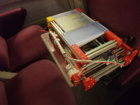
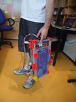
probably a little overkill, but perfect to play a badass bringing a weapon of mass creation x) (or mostly to take the plane with it)
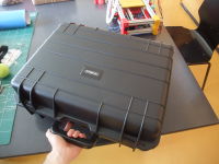
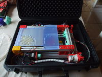
this week I bought that indestructible (can support 900kg) case to see if it fits inside
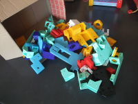
remembering... the pile of tries and revised versions of printed parts... (but not so much as I thought)
this geared stepper have almost the same spacing of a nema14, thus maybe with long holes we can use both
after a day of printing, this first test in real conditions seems successful, not mentioning that lots of peoples liked the machine :)
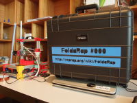
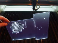
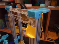
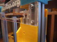
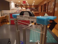
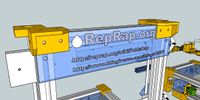
the reprap.org plates are good for indicating the wiki to peoples, not as readable as I'd hope but still good ^^
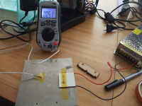
at 12v the peltier-heatbed reach it's temp faster than the hotend (originally used at 19v on the reprappro huxley), thus if you start them at the same time you'll be sure to have the heat spread until the corners of the alu plate :P
installed in few minutes
while the new extruder only did one square test print I took it (again by bike) to a local event, the DIY-Festival, to help hackerspace's friends who where organizing a little workshop to build useless machines
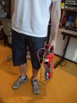
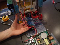
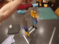
all the way holded in one hand (the machine weight 3-4kg)
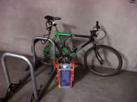
it was my one of my goal, travelling with it by bike : check ;-)
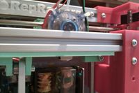
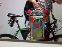
at z=140mm
assemble with the extruder motor on the x-end-idler
add the bearing (it's a rubber roller salvaged from a stratasys cartidge in my case but I'll make one for 624 or 623 bearing)
add the spring and the pneumatic fitting
the new extruder-idler, with a normal spring this time
Second print (video : [30])
later I had to change the step/mm (X-Y was for 14 tooth while I have 16 and Z was for M5 threaded rod while it's M6 here)
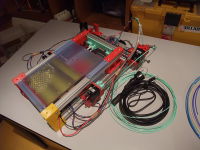
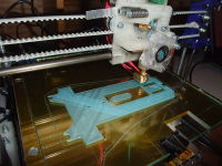
for the very fist print [31], I wanted the open-source-hardware logo ^^ @ 19:15, 24 May 2012 (UTC)

I had to help the extruder by hand, there was not enough pressure from the idler
just received the geared steppers (PG35L-048) from neuhold-elektronik (thanks Kliment for the link!), I'll probably adopt that for the extruder if more power is needed : the torque/resolution of a geared extruder in almost the size of a nema14 ^^
second noodle (with extruder and by hand), cooling seems sufficient, pressure in the extruder idler not enough. And the z-threaded-rods suffer from some misalignment.
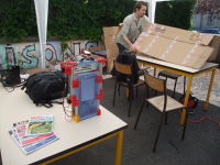
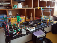
at the hackerspace
^^
now slide without friction http://www.flickr.com/photos/watsdesign/7258799716 or just a little when the x-axis is completed
(zip-ties : aggressive punk look ?)
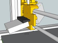
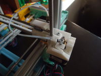
bolting the hotend to the x-carriage (through the fan)
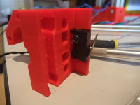
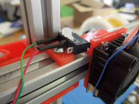
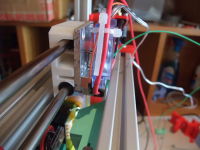
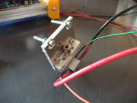
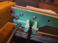
x-endstop integrated to the x-end-motor :)
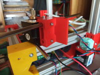
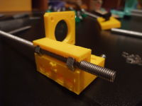
moving the bolts that lock the x-smooth-rods to the side, allowing to remove them at any time. Also improving also the z-friction by placing the two arrows that go in the beam channel closer to the z-threaded-rod, even if I later discovered that the friction mostly came from the XZ frame being a little misaligned due to the pressure of the XZ clamp, but it's now usable).
next I will try that : fan - heat spacer - alu plate (and if not enough, fan - heat spacer - heatsink (the black one) - aluplate)
nonetheless the dissipation is far from enough...
first try, was simple yet perfect for the perpendicularity of the hotend regarding the x-carriage (with the plastic part it always tend to be 1-5° toward the back)
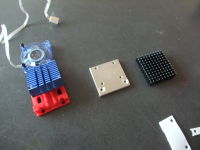
left, the original reprappro hotend; middle and right, possible thing to try for a more compact hotend
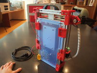
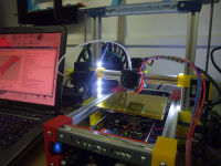
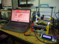
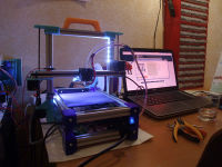
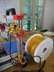
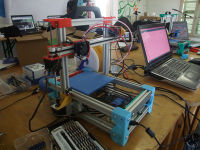
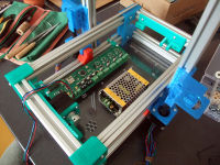
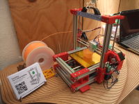
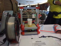
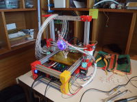
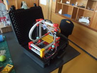
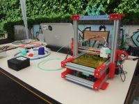
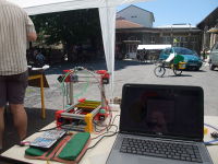
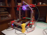
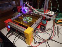
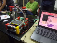
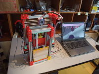
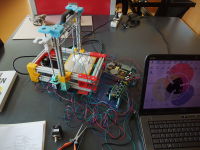
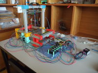
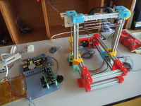
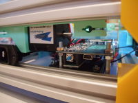
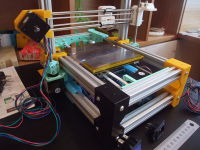
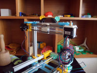
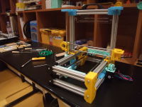
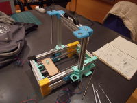
all you need is here, just add a computer to print ^^
(with the previous underplate, but fitted above as a sort of supplementary protection for traveling)
yay :D
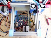
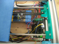
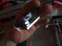
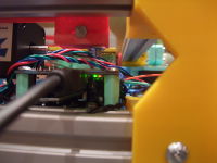
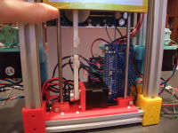
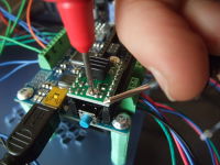
the wiring steps, with the board upside, are way more easier now :)
if we can add a second extruder motor, why not anticipate an eventual future upgrade ^^ (like the reprappro-pcb and the auto-z-levelling)
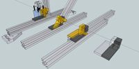
without the previous XZ clamp, it should be possible to use the beam as a guide for the Y-axis (that will save 2 smooth rods, 3 lm6uu and one big RP part, the only one that weren't printable in one piece on the 140x140 bed; saving space too)
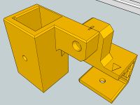
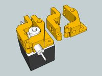
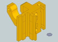
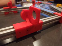
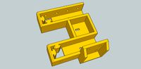
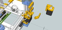
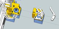
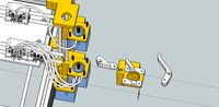
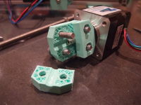
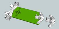
redesigned the first part which I started, the hinge (now in two parts, one is for the hinge, the second hold the motor and replace the XZ clamp, the two are slided on the beam)
then I realized it could help in the assembly, to hold some part or to reduce the number of bolts to secure the beams :)

perfect ! (2nd try, with 0,2mm margin)

trying to print a part to slide on the beams (and discovering that the real beam is somewhat different from the blueprint)
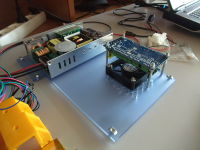
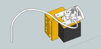
turned the psu 90° ; and got rid of the fan, to place the board with connectors upside (the previous idea was nice but just too much hassle to assemble, and on my eMaker Huxley I don't use a fan or if needed it wouldn't be hard to add one in the space on the left). And the peltier bed work like a charm ^^ (20->60°C in 5-10sec)
tight space
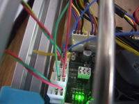
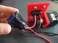
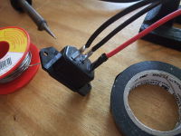
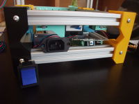
I love this blue switch !
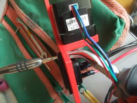
struggling with the wiring of the motors... (in fact the drivers were not at 0.4v but some at 0.7, which explain the pulse)
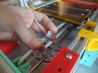
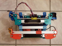
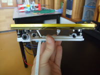
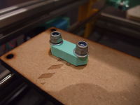
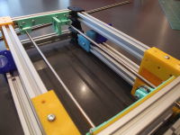
an easy way to assemble and tension the Y-axis :)
hmm finally I start to like this red with the alu and the black motors
ready to be added to the frame :)
use a plier to hold the nut (I've added nut trap now)
fit just an M3 nut and no more ^^'
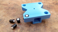
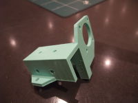
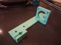
maybe the 4th revision of the Y-motor part (printed, I stop to count the revisions in Sketchup long ago)
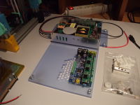
the board will be flipped upside down, but can be left like that for the wiring phase
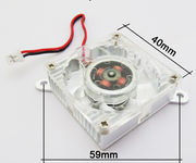
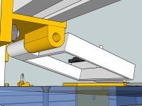
yeah :D I finally found this missing critical part ! A 40x40x10mm fan within an aluminium frame to replace the fan+heatsink in the eMaker/RepRappro hotend and save ~10mm (was a little too big to allow the sliding of the XZ axis in complete storage position). It will also serve to cool the printed part by orientating the fin toward the hotend (the hotend will need a little insulation).
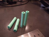
printed spacer, to use the same short bolts as for all the frame (instead of long 45mm bolts)
Everything fit perfectly !!! During this build I'm often surprised by the accuracy of sketchup to reality, when things seems to "just fit", they just fit, and when I discover that something is wrong, I later see that it's also wrong in the model.
when I was a child, I enjoyed making some sorts of lego cars with all the function of a house, even if a "window-grill" seem silly now :p At least I kept the motivation to make compact things ^^
mounting the electronic plate in the tiny space under the bed may be the trickiest part of the build... or maybe not, I just had an idea for the build order that could make it easy and double as a check test of the components :)
the (optional) fan, is placed under the stepper drivers and the y-motor (the board will be reversed to save space)
the underplate replace also two parts that were used to stop the sliding and center the XZ axis
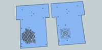
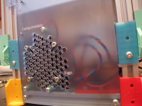
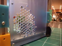
the two models (my favorite is by far the one based on hex holes, but people can make their own pattern ^^), the long holes allow to use a fan from 40 to 60 mm
that also meen struggling sometimes to get the bolt spacing for each fan size
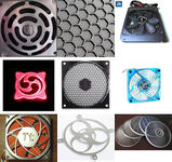
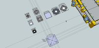
the electronic under-plate is almost finished, I'm now looking for all the existing fan options (low noise)... and a grille pattern :)
now I can hook up the board to play with :) I could upload Marlin but with only one motor it refused to move, I may be obliged to connect everything...
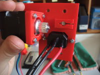
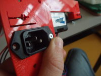
got the model of the plug on traceparts dot com :)
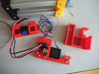
new choice for the arrangement of the electronics : everything on the same side
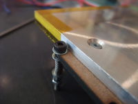
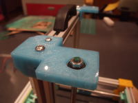
a close-up of one of the three bolts
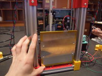
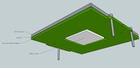
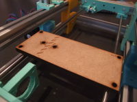
the bed with an eventual glass plate
may need to make some space for the wire to be able to be bended (otherwise they risk to touch the end of the frame toward the y-idler)
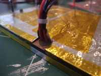
regroup the cables and add more insulation, I had this from an eMaker Huxley but some tape or kapton is certainly fine, it's only required to reach highest temps or save energy
secure it with short counter-sunk screws
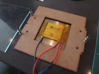
add the insulation-leveling plate (you can add the long bolts with springs at any time)
same for the thermistor
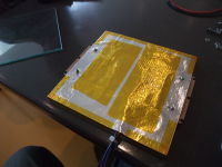
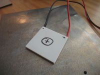
hold the peltier in place with some kapton
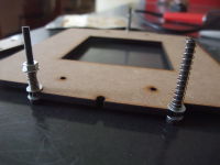
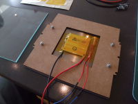
the holes for the screws are side-opened, like for the y-frog, for a quick mount without losing the leveling

adding some heatsink compound to help
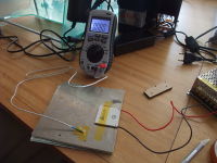
progressively warming-up the bed to 80°C, and probably more with time =)
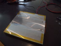
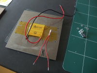
sticked it to the side of the aluminium plate, it quickly reached 50°C
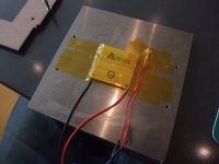
hooked up on 12v to see which face is going hot and which cold
started to remove the original eMaker heated-bed (nicrhome), will be replaced by their pcb-heatbed and the old will be used for the Foldarap (or maybe we can try some ceramic plate ?...)
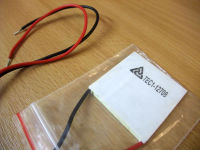
got my peltier element the other day ^^ (and ordered more for the future beta machines)
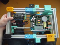
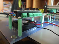
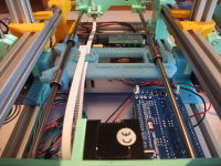
where I want to place everything, accessible from under :) 12v input near the psu, bed output away, usb and reset button toward the back
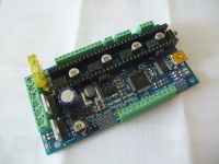
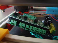
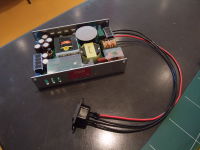
Received the board this morning ! And since we can choose the connectors to solder, I took the opportunity to use screw terminals.
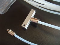
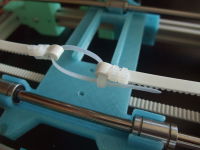
the idler can be mounted toward the x-axis for a flexible 3mm tube, or toward the y-axis (previous pic) for a 4mm tube, which is a little less flexible, but stronger to put new filament beside an old one (that cause my 3mm tube to break on the eMaker Huxley)
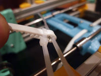
finally, almost perfect ! (video) the simplest extruder idler ? ^^ Looking forward to test that with a real print :)
at least the idler is a short print
hmm, MA-12-04-M6 would be easier to hold(M5 nut have the same diameter than the body of the fitting) : I just put a wall to rely on, since there is an hex slot inside the fitting, it will be easy to assemble in the idler :) (so even if I didn't choose yet between 2 or 4 mm tubing, both can perfectly work).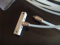
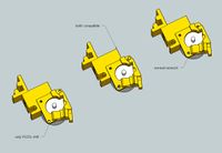
and since they have both an M5 thread, they are compatible with the emaker/reprappro hotend =)
These two models are perfect for 3mm and 4mm tubing, and resist fairly well when pulling on the tube (I didn't managed to remove it by force)
I checked the datasheet before ordering, but I can confirm that 1.75mm filament pass through
yay :D just received the pneumatic fittings this morning !
not attached yet, I need to remove the old heatbed from my eMaker Huxley to use it here (or get an alu plate somewhere)
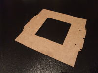
middle hole to accommodate for the peltier element (50x50mm, plus 10mm margin)
second try for the idler, too rigid : maybe with two perimeters instead...

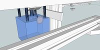
how it should look like (that's not the real bed)
upper max limit : Z=~160mm
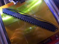
reamed the x-end to fit the 6mm wide belt (reprinted the other end)
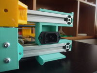
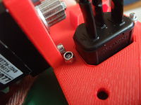
while the opposite front-foot will receive a standard IEC plug
I love this big blue switch. It's supposed to fit inside one of the front-foot (will make some little modification for that)
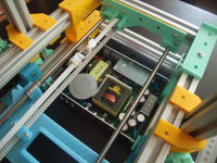
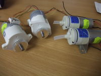
perfect fit for this compact psu :) (finally I choose the costly txh-240-112 but other can fit too)
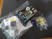
got some stuff from RS today, they ship fast ! (ordered this weekend)
hope it will work :)
I was looking to the reference of the motor in the Up! (nema17 btw), found many interesting user-improvements...inspired by http://www.thingiverse.com/image:111639 I started to rethink the extruder part and came up with that plastic spring idea (far from perfect but you got the principle)
you also have to choose on wich side you like to have access to the bolts/nuts (under is almost always accessible)
slide the y-plate at the middle of the frame, align with the tensioning system and then clamp the belt (can be under or above the y-plate)
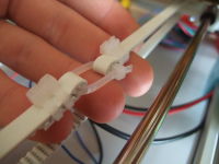
pay attention to the orientation of the zip-ties
make a loop at each end of the belt with zip-ties
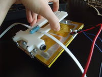
and slide freely :) http://www.flickr.com/photos/watsdesign/6988410463/
open sides for quick release of the bed without loosing the leveling (need test to confirm), while perfectly locked when tightened
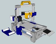
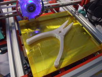
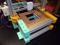
VertX printing the new frog of the FoldaRap :)
frog v3, and all M4 will be in M3 (less weight, one Allen wrench for all)
the emaker huxley belts are 5mm and mine are 6mm wide... need to add 1mm somewhere :p
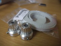
just got some t2.5 belts and alu pulleys ! (easier to have than gt2...)
adding the brass drive gear and a piece of filament, just to show
extruder with a dummy spring
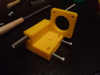
extruder parts for nema14, but also a x-end with a mount for nema17 in case 14Nm wouldn't be enough
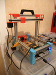
x-axis in place again
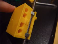
now the nuts fitting is just good :)
that would leave room for up to 3 bowden ^^
why not replace one of the extruder part and the fan by an alu plate ?
freshly printed, I had to pause the print to put the nut in place, the next version will have more room (this one was based on guessed dimension of the nut)
this fifth revision make it :)
the nut holder have a little flex, so I beefed them up and increased the spacing around the nut
back in the fablab after two weeks of bootcamp (reprap/cnc) in Africa
direct drive concept, derived from whosawhatis Minimalistic MK7
and one in two parts, for the smaller size printer
for those who don't have access to a lasercutter but a Mendel-sized 3dprinter
direct drive bowden integrated to the x-end-idler, it's gonna be
awesomequite experimental :D (encouraged by a similar attempt from Brian)
different way to put the bearing in the idler
kept that idea from the VertX x-ends : open nut-holder, allowing to (un)mount the x-end individually at any time (the belt tightening will keep it in place).
many littles things to implement next ^^
making the XZ clamp a little shorter on a side to allow un/mounting while the coupling is in place
printed parts wear now an indication, in an effort for an assembly (almost) without manual
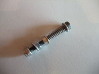
if cut at 240mm, the little bit sticking out of the bearing can receive a nut (not sure if really useful, thrust bearing ? even if the coupling is good ?)
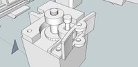
same coupling as on the eMaker Huxley, tweaked to fit 5mm shaft and 6mm threaded rod, works nice :) http://www.youtube.com/watch?v=5kJ6kQqhJVU
the only thing is that it can't be mounted when the z-coupling is here, fail ^^' but a little change will make it
push-fit mounted, it works as is, saving 4 bolt/nuts compared to the previous clamp : adopted
I progressively tested from the light clamp (in case it was sufficient) but finally the heavy one is perfect

but, maybe due to a unfinished print, it's not concentric when fully tightened, will try again...
5mm/6mm version of the three part coupling, hold well the shaft and the rod
let's add a little bit of affordance :)
finally received the motor (Nema14)
thinking about how to manage the extruder now...
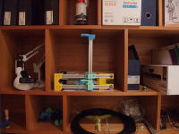
funny that the huxley is just few boxes on the right, hooray for little printers !
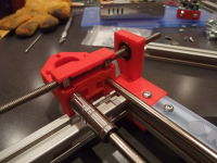
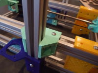
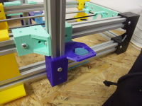
adding the clamp to lock the XZ-axis, no play at all if the lower hinge is also bolted.
lower hinge bolted
smaller clamp to set the sliding limit (and a try for a belt-clamp)
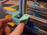
the hinge with clamp, printed

the z axis is driven by only two threaded rods with two nuts, eventually with a spring to avoid backlash (work without on my actual huxley or mendel with VertX
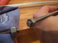
if you are cutting your threaded rods, don't forget to screw a nut near the cut, it will help remake the thread when you will remove it after the cut
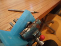
it's possible to insert the bearing by hand, or even easier with a vise. Don't fear to crush the bearing, the printed part is 4mm higher ;)
There was still a little play near the hinge, with that it will be completely immobile, I hope (I think it's already usable, but I want to try that and see if it's perfect then)
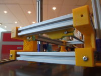
easier to put on, also better against flex along the x-axis (only visible when the vertical beams aren't connected by the top beam)
Even the simplest part seems to work !
trying other clamp ideas (in one piece this time)
now the y-idler and y-motor don't require any centering, just push them against the feets of the right side ^^
always good to test something in real, many ideas and correction arise
it was prooving it's possible to fix the XZ on the lower frame, but I need redesign that to suppress the subtle wobble that came from the hinge (the constraint is too short)
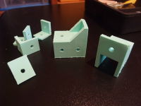
first print-test of the clamps
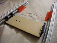
underview of the clamps that limit the sliding movement, for an easy repositioning of the X-axis right in the middle of the Y-axis without thinking about it
almost fit in a stratasys cartridge box :p
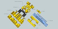
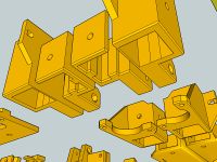
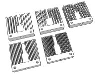
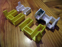
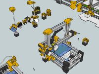
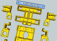
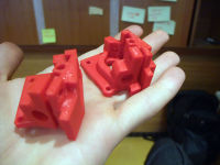
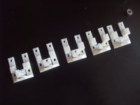
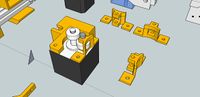
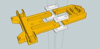
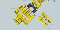
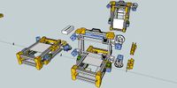
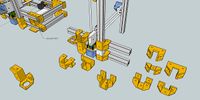
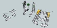
the printed parts that were designed until now, more to come :)
a wall was moved to avoid a bridge (even if it was perfectly printed in the first version), it made me think to add something in that little cavity pointing outward, maybe a switch button to power the reprap and or the heated bed ?
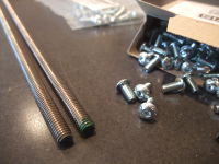
30/01 just received the M6 rods and M4x8 bolts from FixnVis (ordered 26/01) ! Seems to be straight and good quality (A2 steel). With 15€ minimum order I bought more than I needed, but that could serve to make 2-3 kits to offer for beta-testing :)
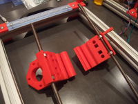
simplicity won (2 parts instead of 6)
the print orientation is good for the rod-clamp function, but it's a little less optimal for the solidity of the bearing and motor holder (under the belt tension... need a good layer bonding)
another idea, is to join the y-axis parts, removing the need to check the spacing between them

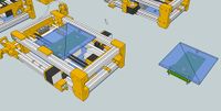
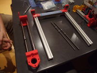
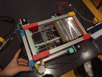
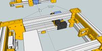
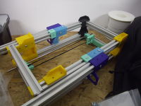
Video : testing the assembly of the frame in one time (took 22min ^^) [40]

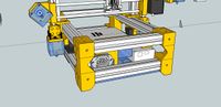
design-in-progress video 1
push-fit connectors for an easy build !
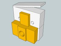
It works as intended alone (but the space for the M8 screw head was too tight, and can be more balanced between the two parts)
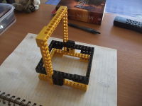
the hinge principle in lego
Now I can start designing the printed parts, especially the hinge.
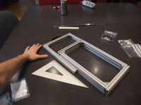
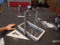
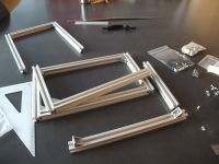
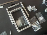
09/01 I ordered the aluminium parts (from KJN) 12/01 Order arrived !! (neat, I would recommend them)
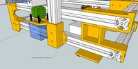
room for the psu/arduino and/or for a Huxley_mini-spool
Finally I'm also searching on the T-slot way, probably more robust than printed parts that may risk to shatter ?


Huxley size
if the same big piece is used on the right side, it may be possible to use a direct-drive-bowden fixed to the x-axis (x-end-idler)
some changes for a more reasonable first iteration (2 z-motors will make the proof of concept easier), and if I want to make something very transportable I may better start with an Huxley-sized machine, taking appart an eMaker Huxley and replacing the rods by these printed parts


Mendel size
http://forums.reprap.org/read.php?283,221591
 Something between a big foldarap and a mondrian
- 5 300mm
- 7 400mm
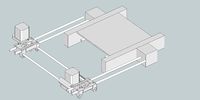
an idea for tensioning the belt between the two z-rods
two bearing to constrain the z-threaded-rod, and maybe no linear-bearing nor smooth-rods
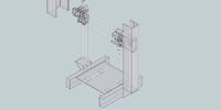
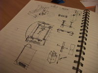
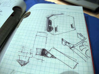
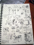
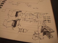
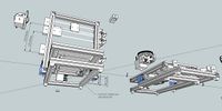
First sketches


From the VertX to a whole printer, it's the next big project I started to dream of, some months ago, because I want to have a folding RepRap for travels/exhibitions/conferences that only need to be plugged to print (even if the Huxley is already not bad for that).
- Foldable (first inspiration came from a folding ladder that my father have, then the Bonsai_RepStrap, this thread where Mendel90 first appeared, and from my Pocket Engraver structure)
- Few threaded rods (I first thought about aluminium extrusion, but finally I'll assemble printed parts to make the frame, which is also good for replication/changes/scaling)
- Easily scalable (can be 300x300x300 or 50x50x50, as we want).
- Sells Mendel style Z-axis (one motor as I like to be able to manually tweak the Z)
More Inspiration
Some details that I found interesting or related or want to integrate to this idea of a foldable machine...


History
- 2011/11: started to design a folding Mendel, then a folding Huxley
- 2012/01: starting to design the Fold-a-slot (actual FoldaRap)
- 2012/05/24: First Print !!
- 2012/06/23: First known user build started by Spacexula :)
- 2012/06/28: beginning of the crowdfunding campaign
- 2012/07: 2-3 more people are starting to build one
- 2012/07/10: the crowdfunding campaign reached 100% ! (30 days left)
- 2012/08/08: the campaign ended at 255% !!! FoldaRap_Batch1 in progress.
- 2012/10 : start of the FoldaRap_Distributed_Manufacturing network
- 2012/10 : another one is being build by Paoparts
- 2012/10 : 1st workshop at Nybicc [43]
- 2012/10/30 : first replication's first print ! (by Joris and his FoldaRap #003)
- 2012/11 : 2nd workshop at Nybicc [44]
- 2012/11 : 3rd workshop at Lille [45]
- 2012/11 : 4th workshop at Dakar [46]
- 2012/12 : 5th workshop at Orléans [47] and first parts produced by a user's machine for the next kits to be delivered :)
- 2013/01 : another US build ! makehacklearn
- 2013/02 : a Japanese Foldarap
- 2013/04 : FoldaRap 1.1
- 2013/04/20 : second crowdfunding campaign
- 2013/07/09 : campaign end at 445% FoldaRap_Batch2 in progress
- 2013/07 : [48] Alex B. is making his own FoldaRap (mendel size), first beta builder of this model :)
- 2013/10/01 : 2nd prototype of FoldaRap 2
- 2014-2016 : FoldaRap 2.5
- 2017/08 : back to the drawing table (FoldaRap 3)
External links, media/press, etc.
I like feedback from the community, but a little attention from a blog or other people is always good :)
- hackaday mention a neat folding reprap, in their article about the many choices of repraps to build
- twittpic of Korben at the NuitDuHack2012
- Paradoxe temporel [49] and [50] also during the NDH2012
- From a little post in the GOALL, to Lorraine numérique / e-alsace
- B3dge
- 3ders.org
- Demonter.net
- Mobile Solar Powered 3D Printer Project on Appropedia (a solar powered foldarap ? :))
- Faveoly
- 3druck
- Bundlr
- Personnal Factory and several other tumblrs
- Fabbaloo
- 3dprinter
- Imastresd
- Nirvasite
- Ponoko
- Makezine
- Genomicon
- Dailygeekshow
- Semageek
- Core77
- Notcot
- Premiere
- Wired
- Nada nos libra de escorpio
- DfRobot
- Usinette&co au Summerlab Nantes
- Atelier-outdoor
- 2013 whishes by OVA design
- Sextoy hacking, from a workshop at the FacLab
- Be-3D, une imprimante 3D portable française
- Disrupt3d
- Sarfata's first steps in 3D Printing with a FoldaRap
- Ping
- Atelier.net
- The RepRap project: an open source/open hardware movement for 3D-printing
- paperblog
- MakerFaire Rome Tour
- Good Morning Crowdfunding
- France Inter, Bienvenue dans la 3ème dimension
- Good Morning Crowdfunding - PDJ
- Cerfav
- MakeHackFab
- Kreizenn-dafar
- Formalab
- Planète-PME
- ITespresso
- FrenchWeb
- La tête dans le flux : les makers
- el diario : Cultura libre y peer production: La era maker
- in the Summer edition of Focus, an Italian magazin about science
- Il Sole 24 Ore
- Maker Faire Rome
- Rue 89
- Futura-Science maker-faire
- REWU 07
- Convention APM 2013
- Anis asso
- birth of the #069 ;-)
- Bubu
- Xevel
- Xevel
- F4GRX
- marie lombard
- 3D Print Show full report
- éveillons-nous
- RepRap Floss Manual
- Poirpom
- France 3 Région Lorraine
- France 3 édition des régions du Journal National
- Management magazine
- La Semaine de Metz : Les pionniers d'un monde libre
- Mosaik.tv
- L'Express
- Une Semaine en Lorraine n°54
- Management Magazine 217
- FabLab Champagneulle
- FabLab Lannion
- Workshop Chemillé
- Workshop Dijon
- Sketchup Scribbles
- OpenAtelier
- HackLab.fr
- Républicain Lorrain
- Milan Design Week
- Stampa3D
- Lorraine Numérique
- TV8
- MJC Apt
- Dydlo OHW
- Feria matematica (1mn05)
- in cover of Comment fabriquer tout et n'importe quoi (translation of "How To Make Almost Anything from Neil Gershenfeld)
- Ceci n'est pas une illusion
- Yes We Are Open!
- Le Parisien Magazine 11.jul.2014
And as is it getting longer and longer, you can follow the tag foldarap on delicious