RepRapPro Huxley Melzi wiring
|
English • العربية • български • català • čeština • Deutsch • Ελληνικά • español • فارسی • français • hrvatski • magyar • italiano • română • 日本語 • 한국어 • lietuvių • Nederlands • norsk • polski • português • русский • Türkçe • українська • 中文(中国大陆) • 中文(台灣) • עברית • azərbaycanca • |
Introduction | Frame assembly | Y axis assembly | X axis assembly | Z axis assembly | Heated bed assembly | Extruder drive assembly | Hot end assembly | Wiring | Commissioning | Printing | Maintenance | Troubleshooting | Improvements
| A notice about these instructions! |
|
These instructions are open to editing by everyone and anyone. |
Contents
- 1 Alternative
- 2 Goal
- 3 Important: general rules for wiring up
- 4 Tools
- 5 Setting the Motor Currents
- 6 Wire routes
- 7 Step 1: The PTFE tube shield
- 8 Step 2: The controller
- 9 Step 3: Power
- 10 Step 4: The stepper motors
- 11 Step 5: Endstops
- 12 Step 6: Hot end
- 13 Step 7: Heated bed signal wires
- 14 Step 8: USB cable
- 15 Step 9: Double check
- 16 Next step
Alternative
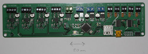
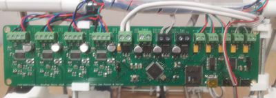
This page describes how to wire up a RepRapPro Huxley that is to be fitted with Melzi Electronics that look like this:
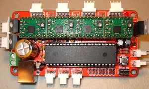
There is a parallel page that describes how to wire up a RepRapPro Huxley that is to be fitted with Sanguinololu Electronics that look like this:
Follow this link for the alternative Sanguinololu wiring page.
Goal
By the end of this stage your machine will be ready to commission.
The electronics will have been temporarily fitted. This allows wire lengths to be set and the machine to start working. It is deliberately rather messy, as this allows wires to be re-routed over and under each other and similar adjustments. The messiness will, of course, be tidied up over the next few instruction pages.
Your will be guided through the print of the final parts needed for your RepRap Huxley to build itself: the clips for holding the controller PCB and the power socket.
You will then remove the temporary attachments and replace them with permanent ones.
Important: general rules for wiring up
You will do serious damage to your RepRap electronics if the power is connected backwards. Other damaging mistakes are to short out high-current devices like motors and heaters, and to connect high-voltage devices like stepper drivers to signal inputs like temperature sensors.
So - in the sections below where it tells you to check things - please check them thoroughly. It is worth taking the time...
Also important for the steps below: when attaching wires to screw connectors, strip about 5mm of insulation off them, twist them between your fingers, and tin them with solder. The tinning is needed for good contact, and to ensure that fraying does not cause shorts.
When wires leave a device (like a motor) or arrive at a connection (like the screw connectors on the controller) leave a small slack length (about 20mm long) for strain relief - don't have the wires taut.
Finally, when making any changes to the wiring or any other electrical aspect of the machine, first disconnect both the power and the USB.
Tools
- Wire strippers
- Soldering iron
- Small screwdriver
- Vice
You will also need a reel of sticky tape.
Setting the Motor Currents
If you have purchased a machine from RepRapPro, this is already been done for you. If not, or if they need adjusting for any reason, this process is described here
Wire routes
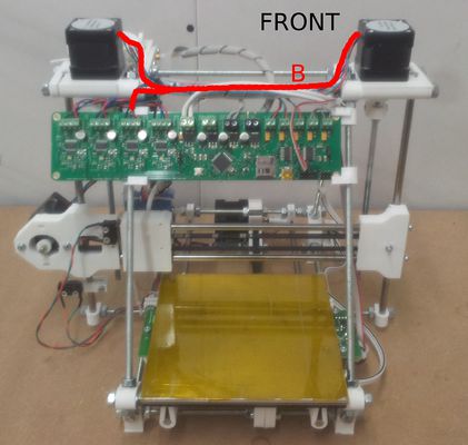
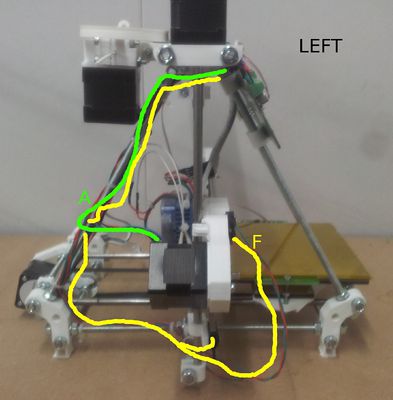
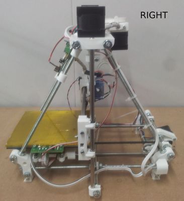
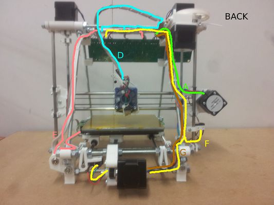
These elevations show the wire routes round the machine. They are referred to in the individual sections below.
The wires will ultimately be attached using coil strip and cable ties. But at this stage attach then using sticky tape (the tape called "pressure tape" works well). If you do this you can build things up incrementally without sacrificing ties when you need to move a wire.
Step 1: The PTFE tube shield
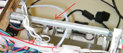
Run a length of the curled wire retaining strip along the back M6 threaded bar at the top. This should completely cover the threads. It prevents the extruder's PTFE tube from rubbing on them.
Step 2: The controller
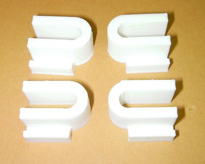
You will need the four printed PCB clips.
Clip the top two onto the frame as near to the top of the M6 threaded rods as you can. The open ends of the clips point outwards. The slots in the clips point downwards.
Offer up the controller PCB to the slots. Offset the printed circuit so that the USB connector (with the black USB cable connected in the picture - don't connect it yet) is just to the left of the right-hand threaded bar.
Push the bottom clips onto the frame to secure the PCB. Take care not to damage any of the soldered components.
All the connectors along the top of the controller are labelled so you can get the right wires in the right connectors. The only exception is the extruder fan - this does not connect to the connector labelled "FAN"; that is for something else. See the extruder wiring section below for more information.
Step 3: Power
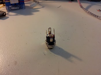
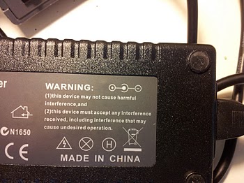
The power from the 19v power supply comes through the connector with positive in the centre and negative around the outside
You will need two power cables in the machine: one about 500 mm long for the controller board, and one about 400 mm long for the heated bed. Both connect to the socket above.
Strip the insulation from the ends of two power wire pairs. For the +19v ends strip about 5mm. For the 0v ends strip about 15mm.
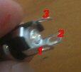
Twist the +19v ends together and tin them. Put a length of heatshrink over both, then solder them to Pin 3 in the picture:
Run the heatshrink down over the pin and shrink it.
Twist the 0v ends together and push the result through Pin 1 , then across and through Pin 2. Keep it clear of Pin 3.
Solder these wires to both Pins 1 and 2. Trim off any excess.
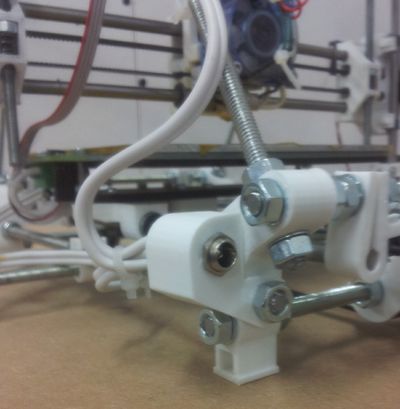
Check that the power connector fits easily into the printed power-connector bracket. Then attach the printer power-connector bracket to the vertex of your Huxley at the back on the left using a 25mm M3 screw, two washers and an M3 nut as shown. Attach the connector to the bracket. (Obviously the wire from the power supply (black) will not yet be plugged in - that picture was taken from a working machine.)
The power wire to the controller board follows the upper path of route E.
Trim the wires to the right length (not forgetting the extra for strain relief - see above), strip the ends, and tin them.
Now plug the power supply into the power connector. Make sure that neither of the free ends of the power leads can short on anything and connect a voltmeter to the ends that you are about to screw into the controller board.
Turn on the power, and make sure that you have +19v and 0v where you expect.
Turn off the power and unplug the power supply.
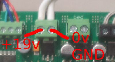
Screw the wires into the power connector of the controller. The 0v (GND) connection is on the right. The +19v is on the left. Check this again with a meter to the outside of the power connector and then to its middle pin.
The power wire to the heated bed follows the lower path of route E. Leave a generous loop so that the bed can run back and forth along its full travel. But don't make the wire so long that it catches on things. Tape it on and try different lengths by hand. Only cut it when its right.
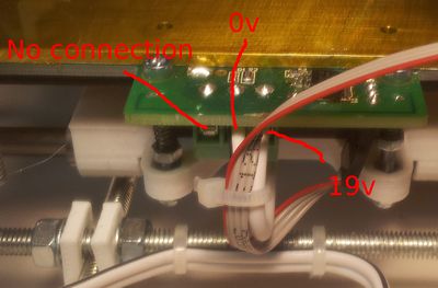
Strip the ends, tin them, and screw them into the heated bed. The 0v (GND) connection is in the middle. The +19v is on the right. There is no connection on the left.
Check that 0v (GND) and +19v on the heated bed are connected to the corresponding points on the controller board with the meter.
Step 4: The stepper motors
Y
Start with the Y stepper wires. These follow route G on the pictures above. Gently twist the wires (not tight) so that they lie neatly together. Tape the wires to the frame every 60/70 mm.
From left to right the colour sequence of the Y-motor wires connecting to the controller is: Red, Blue, Green, Black.
Trim the wires to the right length (not forgetting the extra for strain relief - see above), strip the ends, tin them, and screw them into the "Y-MOTOR" controller connector.
X
Next do the X wires. These follow route A. Again gently twist them. Allow a loop as shown - remember that this will have to accommodate the Z axis as it moves up and down.
From left to right the colour sequence of the X-motor wires connecting to the controller is: Red, Blue, Green, Black.
Trim the wires to the right length (not forgetting the extra for strain relief - see above), strip the ends, tin them, and screw them into the "X-MOTOR" controller connector.
Extruder
Next do the extruder motor wires. These follow the top of route E. Take care that the wires run clear of the extruder shaft attached to the big gear.
From left to right the colour sequence of the extruder-motor wires connecting to the controller is: Black, Green, Blue, Red (that is, the opposite sequence to X and Y).
Trim the wires to the right length (not forgetting the extra for strain relief - see above), strip the ends, tin them, and screw them into the "E-MOTOR" controller connector.
Z
Finally in this section do the Z wires.
The Z-motor wires run along route B.
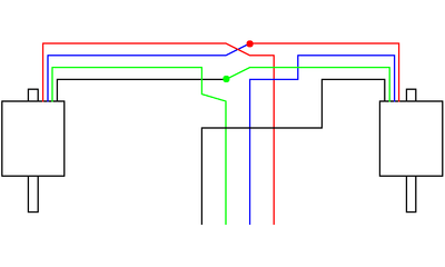
The two Z motors are connected in series as shown above. Cut two 20mm lengths of heat-shrink sleeving and put it on one of each pair of wires that will be connected together. Then twist the ends and solder them, then shrink the sleeving over the join.
From left to right the colour sequence of the Z-motor wires connecting to the controller is: Black, Green, Blue, Red (that is the same as the extruder).
Trim the wires to the right length (not forgetting the extra for strain relief - see above), strip the ends, tin them, and screw them into the "Z-MOTOR" controller connector.
Step 5: Endstops
Connect your endstops using two wires each. It is a good idea to use a different colour for each axis as this will make it easier to get the endstops connected to the correct input. The wires you cut from the stepper motors are different colours...
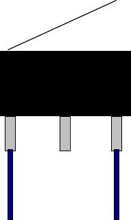
For the limit switch end, crimp or solder a terminal onto the end of the wires, then cover with some heatshrink to insulate the terminal. Connect to the outer pins of the limit switches (the NC = Normally Closed connections; RepRap expects the switch to open when the endstop is hit.)
The endstop switch holes should be drilled out to 3mm diameter so they can be mounted using #4x1/2" self tapping screws (alternatively, #2-56 and M2.2 screws will fit the switch, but are not included).
Y
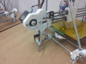
The Y endstop is mounted beside the Y motor:
Its wires follows route F.
Trim the wires to the right length (not forgetting the extra for strain relief - see above), strip the ends, tin them, and screw them into the "YSTOP" controller connector. They can be connected either way - they have no polarity.
X
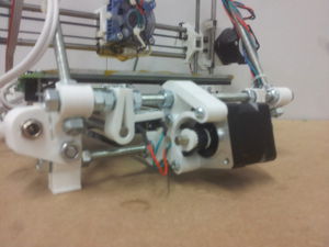
For the X endstop you will need the sticky pad from the extruder fan that you peeled off and saved. Cut a rectangle from it the size of the face of the switch and stick it on so that...
...it will be between the switch and the X-motor end of the X axis. Make sure that the sticky pad does not stick out and so foul the movement of the switch's lever.
Make a small hole in the sticky pad so that you can put a screw through the lower switch hole, then screw the switch to the X-motor end of the X axis.
The wires follow route A. Wind them loosely round the X motor wires.
Trim the wires to the right length (not forgetting the extra for strain relief - see above), strip the ends, tin them, and screw them into the "XSTOP" controller connector. They can be connected either way - they have no polarity.
Z
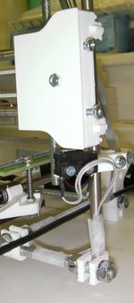
The Z endstop switch is mounted using the "h" shaped printed clip on the right-hand smooth Z bar:
Leave a generous loop of wire between the switch and where you first attach it to the frame. You need to be able to move the "h" clip up and down to set the Z zero position.
The Z switch wires follow route F.
Trim the wires to the right length (not forgetting the extra for strain relief - see above), strip the ends, tin them, and screw them into the "ZSTOP" connector. They can be connected either way - they have no polarity.
Step 6: Hot end
Separate the wires from the heater resistor and those from the thermistor.
Straighten the fan wire (it is quite stiff, and can get kinked). Wrap the heater resistor wires round the fan wire. It is neatest to do these together, one going clockwise and the other anti-clockwise.
Loop the heater and fan wires behind and over the top of the threaded bars across the top of the machine (the wires don't run between the bars). Give a generous loop - remember that the X axis has to run from end to end when the Z axis is at the bottom of its travel. Tape the wires to the middle of the front bar.
You marked the fan wires positive and negative when you cut the connector off them. Trim them to the right length (not forgetting the extra for strain relief - see above, and not forgetting which is positive and which is negative), strip the ends, and tin them. Loosen the power wires and and screw them and the fan wires back into the main power connector. Make sure you get the polarity right.
The fan wires do not connect to the connector marked "FAN". That is for a different optional fan for cooling prints as they are being built from materials that require that.
Run the heater resistor wires to the "HOTEND" connector. Trim the wires to the right length (not forgetting the extra for strain relief - see above), strip the ends, tin them, and screw them into the "HOTEND" connector. They can be connected either way - they have no polarity.
Wind the thermistor wires round the fan wires in the same way as you did the heater wires. Run them to the "ETEMP" connector. Trim the wires to the right length (not forgetting the extra for strain relief - see above), strip the ends, tin them, and screw them into the "ETEMP" connector. They can be connected either way - they have no polarity.
Step 7: Heated bed signal wires
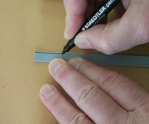
If your ribbon cable does not have a coloured stripe you can easily add one with a felt-tipped pen:
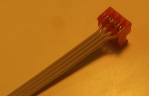
Take the 4-way ribbon cable. Separate the wires at one end for about 15mm.
Push the separated wires into the 4-way insulation displacement connector (IDC). There is no need to strip the wires. Use the jaws of the vice to push the connector together. Be gentle - don't damage the connector by pushing too far.
Plug the connector onto the 4-way pin header on the heated bed at the right in this picture:
The ribbon cable follows route E.
Only three of the four wires are used (the fourth is for a future enhancement for bed levelling for which your machine is already pre-configured). The unused wire is the nearest to you in the picture.
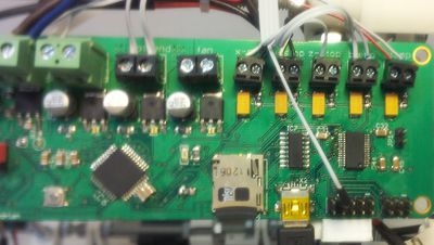
The next wire in is the signal that turns the heated bed MOSFET on and off. That needs to be connected to a pin on the expansion header as shown below (top row, second pin in from the left):
As you can see, "HOTBED" connector is not connected to anything, since we are using the bed mounted MOSFET to control the heatbed.
The final two wires (the two furthest away in the first picture) go to the connector labelled "BTEMP". The wire connected to the innermost pin on the heatbed PCB is GND. This should be screwed into the BTEMP connector, in the side nearest the ETEMP connector. The next wire in the ribbon cable connects to the other side of the BTEMP connector.
Step 8: USB cable
The USB cable plugs into the mini-USB connector beside the SD card socket on the controller. The cable follows route C.
Step 9: Double check
Use your meter to double-check the power connections.
Make sure that 0v (GND) - the outside of the power connector - runs to the places in the circuitry that you would expect (for example the case of the SD card socket).
Check that the +19v wires run from the central pin on the connector to the right places on the circuit boards.
Check the continuity of the connections to the heated bed with a meter from the screw connections on the controller board to the little blobs of solder on top of the 4-way connector. If you have open-circuit problems, it may be the IDC. A neat trick with this to rectify an open circuit (thanks to Alan Ryder) is gently to pull the IDC apart, take the wires out, strip them, and tin them. Then reassemble - the tinning ensures good contact with the IDC blades. This is only worth doing if you have problems with the simple method, though.
You did set the motor currents, as described above, didn't you?
