Calibration issue with Delta printer
Posted by Nate523
|
Calibration issue with Delta printer March 30, 2016 07:52PM |
Registered: 8 years ago Posts: 89 |
Hey guys,
wondering if you can help me, according to this:
[www.reddit.com]?
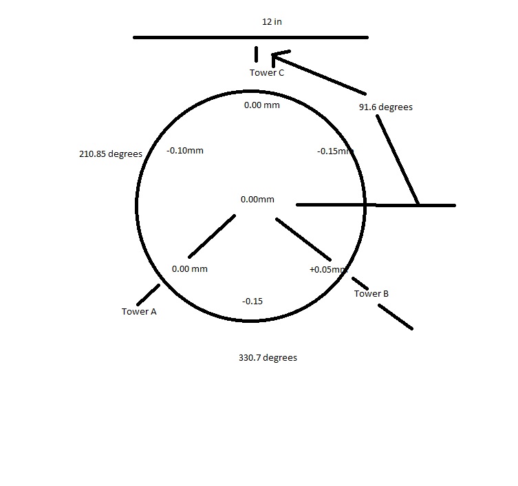
once I get my gaps between the towers calibrated to near or exactly equal that all I have to do is adjust the steps per mm to get them to match up with everything else. However, I have adjusted the steps per mm till I start pulling my hairs out, I still get the same errors on the bed. I've attached a crude drawing of how far off some points are, I'm just wondering if anyone has had success in making the build surface flat or at least calibrating the firmware with repetier to be flat as possible? Thanks
wondering if you can help me, according to this:
[www.reddit.com]?
once I get my gaps between the towers calibrated to near or exactly equal that all I have to do is adjust the steps per mm to get them to match up with everything else. However, I have adjusted the steps per mm till I start pulling my hairs out, I still get the same errors on the bed. I've attached a crude drawing of how far off some points are, I'm just wondering if anyone has had success in making the build surface flat or at least calibrating the firmware with repetier to be flat as possible? Thanks
|
Re: Calibration issue with Delta printer March 30, 2016 11:33PM |
Registered: 8 years ago Posts: 916 |
This error can be caused by either steps per mm being well off, or twist in the frame.
Adjust steps per mm by either calculation, or by using a caliper to measure how far your carriages move when you command a 100mm move in the Z direction.
Twist in the frame needs careful measurement with a large square. I used turnbuckles on two faces to get the twist out of my frame.
While you're there, have a look at how parallel your towers are. They need to be as precise as you can get them (0.1mm difference at absolute MOST, prefer 0.05mm difference).
|
Re: Calibration issue with Delta printer March 30, 2016 11:50PM |
Registered: 8 years ago Posts: 89 |
Well, I have adjusted teh steps per mm to get pretty much an accurate cube, like within .15mm depending on extrusion. So I don't think that is my major problem.
Could you explain to me what you mean by parallel? I've heard this before but parallel to what exactly?
I don't have a large square, I will have to go purchase one, twisting is a new one that I haven't heard so that is very helpful, though I don't know how to implement turnbuckles into this printer. Thanks for your advice, I really appreciate it
|
Re: Calibration issue with Delta printer March 31, 2016 12:56AM |
Registered: 8 years ago Posts: 916 |
Don't adjust steps per mm to get a perfect cube. That's well and truly the wrong approach for a delta. Steps per mm must be set so that your carriages move the right amount for a given command. You should also set your diagonal rod length to be exactly how long it is, from centre of ball to centre of ball. Don't adjust steps per mm or diagonal rod length to adjust your part size. There are many factors that affect part size, but the previous two numbers are not what you should adjust. Once you get your frame 100% square, parallel, no effector tilt, and your extrusion calibrated nicely, then you'll get perfectly sized parts. Trust me, I've been through this battle with two Deltas. I've tried those two adjustments. Down that path lies madness.
To get your towers parallel you need to measure the distance between them, using a vernier. I use the depth measurement function on my verniers, and measure between towers both top and bottom. All 6 measurements (top and bottom of X-Y, Y-Z and Z-X) should be within 0.05mm. You need to physically adjust the frame.
Twist is where when you look down from the top of the frame, the top triangle doesn't exactly line up with the bottom, it's twisted a bit. The only real way to get this out is by adding diagonal bracing that you can adjust. I used wire and turnbuckles that make a big X on two faces (Y-Z and Z-X). I can stick a big square on the base extrusions, and adjust the turnbuckles until all angles are square. This is tedious and repetitive, but works.
You might also get more help asking in the delta machines forum.
Good luck.
|
Re: Calibration issue with Delta printer March 31, 2016 01:22AM |
Registered: 8 years ago Posts: 89 |
Thanks that makes sense about the steps per mm, because I was pulling my hair out getting weird results adjusting that and the diagnol rod length. I finally switched my steps per mm accordingly with my belts, pully's and steps for nem 17 motosrs, and that made a huge improvement to my parts.
If I am understanding you correctly, we are making sure that the towers are parallel to each other as far as there length goes.... now I feel a little dumb. Thanks for explaining that though, I obviously needed it. I don't have calipers that big, so I will have to invest in some and see what I can do about that.
The twist seems like a big chore that I don't think that I am equipped to deal with yet, but thanks for all your input, it at least points me in a sensible direction. Its more information than I have been able to find so thanks a ton!
|
Re: Calibration issue with Delta printer March 31, 2016 02:28AM |
Registered: 10 years ago Posts: 14,672 |
You may find my delta printer calibration calculator at [www.escher3d.com] useful, especially for getting the tower angle corrections right. As Nebbian says, leave the steps/mm and diagonal rod length alone
Large delta printer [miscsolutions.wordpress.com], E3D tool changer, Robotdigg SCARA printer, Crane Quad and Ormerod
Disclosure: I design Duet electronics and work on RepRapFirmware, [duet3d.com].
Large delta printer [miscsolutions.wordpress.com], E3D tool changer, Robotdigg SCARA printer, Crane Quad and Ormerod
Disclosure: I design Duet electronics and work on RepRapFirmware, [duet3d.com].
|
Re: Calibration issue with Delta printer March 31, 2016 03:05AM |
Registered: 8 years ago Posts: 916 |
Quote
Nate523
If I am understanding you correctly, we are making sure that the towers are parallel to each other as far as there length goes.... now I feel a little dumb. Thanks for explaining that though, I obviously needed it. I don't have calipers that big, so I will have to invest in some and see what I can do about that.
The twist seems like a big chore that I don't think that I am equipped to deal with yet, but thanks for all your input, it at least points me in a sensible direction. Its more information than I have been able to find so thanks a ton!
A normal set of 150mm calipers should work. When you pull the jaws apart, a little metal rod extends out the bottom. Use that on one tower, and the top jaw on the other tower. Zero your caliper. Now measure elsewhere, and the caliper will tell you how far out you are.
Twist is easy to measure, just use a large square and measure between a tower and one bottom extrusion, then between the same tower and the other extrusion. If one side is acute, and the other obtuse, then you've got twist.
I should really write all this up with pictures and post it somewhere.
|
Re: Calibration issue with Delta printer March 31, 2016 03:11AM |
Registered: 10 years ago Posts: 14,672 |
Quote
nebbian
A normal set of 150mm calipers should work. When you pull the jaws apart, a little metal rod extends out the bottom. Use that on one tower, and the top jaw on the other tower. Zero your caliper. Now measure elsewhere, and the caliper will tell you how far out you are.
Great idea - why didn't I think of doing that?
Large delta printer [miscsolutions.wordpress.com], E3D tool changer, Robotdigg SCARA printer, Crane Quad and Ormerod
Disclosure: I design Duet electronics and work on RepRapFirmware, [duet3d.com].
|
Re: Calibration issue with Delta printer March 31, 2016 02:29PM |
Registered: 8 years ago Posts: 89 |
Pictures would be nice I m currently waiting on a set of vernier calipers to check my parralel towers, might get a square today for the twisting, can you guys maybe explain this a bit more because I'm still not getting the way you guys are using a square to measure the twist? Appreciate the help guys!
I m currently waiting on a set of vernier calipers to check my parralel towers, might get a square today for the twisting, can you guys maybe explain this a bit more because I'm still not getting the way you guys are using a square to measure the twist? Appreciate the help guys!
|
Re: Calibration issue with Delta printer March 31, 2016 02:38PM |
Registered: 9 years ago Posts: 483 |
|
Re: Calibration issue with Delta printer April 01, 2016 02:15AM |
Registered: 8 years ago Posts: 89 |
Well I'd rather wait for those calipers to check, I don't feel like getting an object that is perfectly the right size to fit.
DC42 I tried your calibration tool, but I don't know if I am doing it correctly, in repetier they refer to towers x y z as A B C, and I'm not sure your angle corrections are the angle from the positive x axis to the tower x, y or z. Can you clarify? I'm also assuming the enstop corrections, are in steps per mm because thats the way the repetier firmware has it, or are they in mm and I am supposed to physically move the endstops?
DC42 I tried your calibration tool, but I don't know if I am doing it correctly, in repetier they refer to towers x y z as A B C, and I'm not sure your angle corrections are the angle from the positive x axis to the tower x, y or z. Can you clarify? I'm also assuming the enstop corrections, are in steps per mm because thats the way the repetier firmware has it, or are they in mm and I am supposed to physically move the endstops?
|
Re: Calibration issue with Delta printer April 01, 2016 03:05AM |
Registered: 10 years ago Posts: 14,672 |
The angle corrections are the changes from the nominal positions 120 degrees apart, in an anticlockwise direction as seen from above. I am aware that in Repetier you configure the absolute tower angles. You need to add the corrections from the calculator to the standard angles and put thosee figures into the Repetier configuration tool.
When you select Repetier firmware in the calculator, the endstop corrections are in steps. Otherwise they are in mm. You don't need to physically move the endstop switches unless the corrections are very large e.g. more than 2mm.
Large delta printer [miscsolutions.wordpress.com], E3D tool changer, Robotdigg SCARA printer, Crane Quad and Ormerod
Disclosure: I design Duet electronics and work on RepRapFirmware, [duet3d.com].
|
Re: Calibration issue with Delta printer April 01, 2016 03:08AM |
Registered: 8 years ago Posts: 89 |
|
Re: Calibration issue with Delta printer April 01, 2016 03:14AM |
Registered: 10 years ago Posts: 14,672 |
Two suggestions:
1. Check that you are entering the height errors with the right sign. Some people get them reversed.
2. If in doubt, start with 4 factor calibration using one point in front of each tower and one in the centre. That replicates the standard manual calibration procedure, but converges much more quickly.
Large delta printer [miscsolutions.wordpress.com], E3D tool changer, Robotdigg SCARA printer, Crane Quad and Ormerod
Disclosure: I design Duet electronics and work on RepRapFirmware, [duet3d.com].
|
Re: Calibration issue with Delta printer April 01, 2016 03:32AM |
Registered: 8 years ago Posts: 89 |
|
Re: Calibration issue with Delta printer April 01, 2016 04:02AM |
Registered: 8 years ago Posts: 89 |
Except the way I did it was using repetier to calibrate my endstops by using a rod that I have to set the carriages at equal height and give the g132 s2 command to set th endstop offsets, then set the bed to that, but now the bed looks like it isn't level, and I know it isn't level to the towers because my triangle that I have shows they are off..... I really feel like I get the stuff in th emiddle that I am supposed to do for calibration and such, but there are things that I have completely missed such as the parallel portion of the towers, their twist, etc.. things that need to be checked and adjusted before I start messing with the printer on.
|
Re: Calibration issue with Delta printer April 01, 2016 04:07AM |
Registered: 8 years ago Posts: 89 |
|
Re: Calibration issue with Delta printer April 01, 2016 04:55AM |
Registered: 8 years ago Posts: 916 |
Hi Nate,
Here's how you measure and eliminate twist.
You need to put your square flat on the horizontal extrusion in two directions (I didn't quite line it up properly due to the bed being in the way, normally to measure this properly you'd take the bed off). When both directions are at 90 degrees then you're good to start measuring the other towers.
You can see here the diagonal wires I put in, to adjust the squareness of the towers.
Here's how you measure and eliminate twist.
You need to put your square flat on the horizontal extrusion in two directions (I didn't quite line it up properly due to the bed being in the way, normally to measure this properly you'd take the bed off). When both directions are at 90 degrees then you're good to start measuring the other towers.


You can see here the diagonal wires I put in, to adjust the squareness of the towers.
|
Re: Calibration issue with Delta printer April 01, 2016 05:04AM |
Registered: 10 years ago Posts: 14,672 |
Quote
Nate523
When you say right signs, the way I understand it, is that my z max is when I home the machine say it is now at 600mm. Then when I bring it down to the bed, I get a number say like .2mm for it to touch the bed. That would mean it is positive 0.2 for that point measurement correct?
If the nozzle is touching the bed when the indicated height is 0.2mm instead of 0mm, then the nozzle is too low, and you have a negative height error at that point.
Large delta printer [miscsolutions.wordpress.com], E3D tool changer, Robotdigg SCARA printer, Crane Quad and Ormerod
Disclosure: I design Duet electronics and work on RepRapFirmware, [duet3d.com].
|
Re: Calibration issue with Delta printer April 01, 2016 10:56AM |
Registered: 8 years ago Posts: 356 |
You guys said dont touch the rod length but if you use dc42 calculator factor 7 it will change it to something else. the calculator after many iteration put mine 5mm longer than they really are and the calculator also touch my delta radius . But after all calibration done I still print my 100mm part at +/- 0.2 with very minimal cartesian correction ( 0.995 ish on Y and Z only , X was spot on). DC42 correction is the way to go do it many time in a row , I did 3 or 4 time factor 7,10 point in my case.
I kind of envy you guys with small delta, I wish I can use a 6 inch vernier to get measurement between tower.. in my case its in the 45 cm range so its expensive a vernier that size, I had to use a regular metal rule, must be not so bad since I end up with tower correction ( X-0.32 Y-0.03 Z0.00 )
After a month I still dont have a z probe, only no adjustable micro switch endstop and did not redo once the bed calibration and still print flat, I even move the printer to another room. Im starting to wonder what all the fuzz about doing the z probe each print...
|
Re: Calibration issue with Delta printer April 01, 2016 11:35AM |
Registered: 8 years ago Posts: 89 |
Nebbian,
Thanks for showing that! Makes a lot more sense now, I'm curious though doesn't that affect your parrallelity of the towers when you adjust the twist? Or are you adjusting the turnbuckles so that all towers twist the right amount?
GroupB hats weird hat it was adjusting your rod length, it doens't adjust mine when I use it, that's strange. I'd be curious how you set up your printer, because mine is a large one as well. Build dimensions are 280mm diameter and 5-600mm height. Though I havent been able to use the whole build area because of calibration issues
|
Re: Calibration issue with Delta printer April 01, 2016 11:36AM |
Registered: 8 years ago Posts: 89 |
|
Re: Calibration issue with Delta printer April 01, 2016 11:58AM |
Registered: 8 years ago Posts: 89 |
|
Re: Calibration issue with Delta printer April 01, 2016 12:17PM |
Registered: 8 years ago Posts: 356 |
Nate I did the same error at first when using DC calibration .. if you see 0.2 too high you enter -0.2
The factor 7 do play with delta radius and rod length , I went straight to factor 7 but maybe the result with only factor 4 or 6 is the same .. whats important is the end result... if its printing accurate If I had to redo it , Ill probably start with 2 factor 6 then 1 factor 7 to finish 10 point on the bed for both.
My head have the clearance to move in a 330mm diameter but im using only 300 right now because when I design it I was not aware of the minimal 20 ish degree the rod have to be at minimum. My height is 400 ish mm close to 16 inch, its tall enough for me, longer than that I was afraid to run into belts trouble and since its my first one I play it a little more safe but height is easy enough to add to a delta as an upgrade if needed.
You can see my build/progress fixing all my problem I had thread in the delta section " All metal delta "The Imp"" but my printer is a custom design/made I did not had any twist or squareness of the frame to fix due to my design, only tower position and since my bed sit on the frame itself because I dont use a heatbed but soon a heated enclosure no bed leveling was requite too.
I did the basic check the measurement between tower ( front to front corner and rear to rear corner( I use 20X40 so its kinda a twist check in same time)), check if the tower were square with my machinist square, align all my balls ( magnetic joint) on all carrier and also on effector the same, then did DC calibration, it took me a entire day only to measure and move tower then measure again make them all the same distance.
Just take your time don't rush it, calibration of the frame is critical
The factor 7 do play with delta radius and rod length , I went straight to factor 7 but maybe the result with only factor 4 or 6 is the same .. whats important is the end result... if its printing accurate
If I had to redo it , Ill probably start with 2 factor 6 then 1 factor 7 to finish 10 point on the bed for both.My head have the clearance to move in a 330mm diameter but im using only 300 right now because when I design it I was not aware of the minimal 20 ish degree the rod have to be at minimum. My height is 400 ish mm close to 16 inch, its tall enough for me, longer than that I was afraid to run into belts trouble and since its my first one I play it a little more safe but height is easy enough to add to a delta as an upgrade if needed.
You can see my build/progress fixing all my problem I had thread in the delta section " All metal delta "The Imp"" but my printer is a custom design/made I did not had any twist or squareness of the frame to fix due to my design, only tower position and since my bed sit on the frame itself because I dont use a heatbed but soon a heated enclosure no bed leveling was requite too.
I did the basic check the measurement between tower ( front to front corner and rear to rear corner( I use 20X40 so its kinda a twist check in same time)), check if the tower were square with my machinist square, align all my balls ( magnetic joint) on all carrier and also on effector the same, then did DC calibration, it took me a entire day only to measure and move tower then measure again make them all the same distance.
Just take your time don't rush it, calibration of the frame is critical
|
Re: Calibration issue with Delta printer April 01, 2016 01:57PM |
Registered: 8 years ago Posts: 89 |
Thanks a lot guys! I can't do much till I get the equipment to measure stuff with, need an L-Square for the twist, I have a triangle that might work but I want a steel square to make sure triangle i snot that big so it doesn't show me much in the way of errors. I am going to focus right now on making sure my bed is absolutely flat, it is a glass plat on a PCB heating bed, so as far as its own flatness I'm pretty sure it is okay, but I think my methods of making sure the bed itself is level is lacking so that might not be helping. Going to take a steel ruler and make sure that each point of the bed is at the same height. Then when I get my caliper that is big enough, I am going to take off the top portion of the 3d printer try to adjust the towers as best as I can there, then put the top back on loosen screws and let it settle, re-install, check shim and see if I can setup something for the twist if it seems to be a problem, and hopefully get the frame all squared out. Seems a lot of work but my wife and I bought this thing so we can use the whole volume to print wearable armor and such, so I am trying to make it worth the money I will keep you guys updated.
I will keep you guys updated.
|
Re: Calibration issue with Delta printer April 01, 2016 02:12PM |
Registered: 9 years ago Posts: 483 |
|
Re: Calibration issue with Delta printer April 01, 2016 02:14PM |
Registered: 8 years ago Posts: 89 |
|
Re: Calibration issue with Delta printer April 01, 2016 06:50PM |
Registered: 9 years ago Posts: 483 |
|
Re: Calibration issue with Delta printer April 01, 2016 06:55PM |
Registered: 8 years ago Posts: 916 |
|
Re: Calibration issue with Delta printer April 01, 2016 08:27PM |
Registered: 8 years ago Posts: 356 |
If you buy a L square, get a machinist one.. even a 3 inch will do ( bigger is better) and they super accurate vs carpenter one. Then maybe a cheap not digital metal angle protractor a little bit bigger so you can 90 degree the protractor with the square and its useful to check 60 degree or part you will make.
You will be surprise when you measure a carpenter one with a machinist square how off they are, specially the adjustable kind.
Before I went into building my printer I got me all those , machinist square, protractor, metal rule 0.5mm and a 0.0005" digital Dial with data output ( If I want one day to map the bed) and off course my old caliper , all useful stuff that you can also use later to measure part you will make too.

Sorry, only registered users may post in this forum.