Prusa i3 Hephestos
|
English • العربية • български • català • čeština • Deutsch • Ελληνικά • español • فارسی • français • hrvatski • magyar • italiano • română • 日本語 • 한국어 • lietuvių • Nederlands • norsk • polski • português • русский • Türkçe • українська • 中文(中国大陆) • 中文(台灣) • עברית • azərbaycanca • |
Release status: working

| Description | |
| License | |
| Author | |
| Contributors | |
| Based-on | |
| Categories | |
| CAD Models | |
| External Link |
Translation in progress. Please visit Spanish version.
http://reprap.org/wiki/Prusa_i3_Hephestos/es
Contents
- 1 Introduction
- 2 Galery
- 3 Thecnical specifications
- 4 Changes with respect to other models Prusa i3
- 5 Printed pieces
- 6 Bill of Materials
- 7 Assembly Guide
- 7.1 Required tools not included in the BOM
- 7.2 Preparation before assembly
- 7.3 Axis assembly
- 7.3.1 X Axis
- 7.3.1.1 Enter bearings
- 7.3.1.2 Prepare the tensor X Axis
- 7.3.1.3 Enter the X Axis tensor
- 7.3.1.4 Introduce smooth rod bearings
- 7.3.1.5 Prepare the X Axis Endstop sensor
- 7.3.1.6 Introduce the X Axis Endstop sensor in the smooth rod
- 7.3.1.7 Introduce the smooth rod in the side parts
- 7.3.1.8 Mount the X Axis motor
- 7.3.1.9 Introduce the adjustment screw for the X Axis Endstop
- 7.3.1.10 Introduce the pulley on the X Axis motor
- 7.3.2 Z Axis
- 7.3.2.1 Couple the motor hold on the frame
- 7.3.2.2 Couple the Z motors
- 7.3.2.3 Attach the top tether of smooth rods
- 7.3.2.4 Prepare the Z Axis Endstop
- 7.3.2.5 Union X Axis with Z Axis: Insert threaded rods
- 7.3.2.6 Union X Axis with Z Axis: Introduce smooth rod
- 7.3.2.7 Union X Axis with Z Axis: Union with X Axis:
- 7.3.2.8 Union X Axis with Z Axis: Flexible coupling
- 7.3.2.9 Union X Axis with Z Axis: Z Axis Endstop
- 7.3.3 Y Axis
- 7.3.3.1 Preparation of M10 threaded rod
- 7.3.3.2 Preparation of smooth rods
- 7.3.3.3 Union of smooth rods with threaded rods
- 7.3.3.4 Secure with nuts
- 7.3.3.5 Secure with flnages
- 7.3.3.6 Preparation of Y Axis tensioner
- 7.3.3.7 Preparation of Y Axis motor
- 7.3.3.8 Preparation of the threaded rods M8 - Part 1
- 7.3.3.9 Preparation M8 threaded rod - Part 2
- 7.3.3.10 Union of the rods
- 7.3.3.11 Secure with nuts the structure
- 7.3.3.12 Preparation of the aluminum base
- 7.3.3.13 Secure the base aluminum with flanges
- 7.3.3.14 Prepare the Endstop of the base
- 7.3.3.15 Secure the Endstop at the base
- 7.3.3.16 Place the belt of the Axis Y
- 7.3.3.17 Tighten all nuts
- 7.3.3.18 Place the methacrylate base
- 7.3.3.19 Prepare the Y Axis Endstop on the frame
- 7.3.3.20 Secure the Y Axis Endstop on the frame
- 7.3.3.21 Union Y Axis with the X and Z axes: Snap axes
- 7.3.3.22 Union Y Axis with the X and Z axes: Fit and tighten nuts
- 7.3.4 Extruder
- 7.3.4.1 Prepare the carriage
- 7.3.4.2 Place the carriage in the X axis
- 7.3.4.3 Secure the carriage with a flange
- 7.3.4.4 Place the belt on the X Axis
- 7.3.4.5 Screw the Extruder support
- 7.3.4.6 Montar el Extrusor
- 7.3.4.7 Placing the blower nozzle and Hot end security
- 7.3.4.8 Place the glass on the base
- 7.3.5 Electronic
- 7.3.5.1 Place the RAMPS 1.4
- 7.3.5.2 Preparar el panel de control LCD
- 7.3.5.3 Montar el panel de control LCD en el marco
- 7.3.5.4 Meter los cables en la cadenenta del Eje X
- 7.3.5.5 Colocar la cadeneta del Eje X
- 7.3.5.6 Meter los cables del Eje Z y colocar la cadeneta del Eje Z
- 7.3.5.7 Preparar el ventilador
- 7.3.5.8 Conexionado y guiado de los cables
- 7.3.5.9 Colocar el ventilador
- 7.3.5.10 Colocación del soporte para la bobina de filamento
- 7.3.1 X Axis
Introduction
- Prusa 3D printer Hephestos is a free project 'designed and developed by the Department of Innovation and Robotics bq'. Hephestos is based on the Prusa i3 and adds several improvements learned from other printers as PowerCode users of the RepRap community, modifications to these parts and designs own department.
- This project has sought to offer a robust printer design that solves many of the shortcomings of earlier designs such as the subjection of the limit switches and cable routing. We have placed particular emphasis on providing good documentation to facilitate and more comfortable to the user installation and commissioning of the printer.
- The complete kit can be purchased on the website http://store.bqreaders.com/es/diy/.

Mounting Video (Youtube):
<videoflash type="youtube">eb74i006XIw</videoflash>
Galery


Thecnical specifications
Dimensions
- -Dimensions printer: (x) 460 x (y) x 370 (without roll z) 510 (with roll z) 583 mm
- -Dimensions printer area : (x) 215 x (y) 210 x (z) 180 mm
- -Dimensions box: (x) 400 x (y) 400 x (z) 250mm
Mechanical
- -Frame aluminum base and powder coated
- -Bars X cars for hard chrome, Y, Z
- -Linear ball bearing LM8UU for X, Y, Z
- -Axial B623ZZ bearing pulleys balls for X, Y
- -Igus Energy Chains
- -Flexible Couplings threaded rods of Z axis
- -System level print base with 4 points and cushioning
- -System quick change print base with Clips
- -Fans brushless axial ball bearings.
Print resolution
- -Very high: 60 microns
- -High 100 microns
- -Media 200 microns
- -Low 300 microns
Extruder Mechanics
- -Extruder own
- -0.4mm nozzle
- -Sink fins with axial fan
- -Irrigation Nozzle Part
Print speed
- -Recommended speed: 50 mm / s
- -Maximum recommended speed: 80 mm / s
Electronics
- Any RepRap electronics conforming to RepRap Interface Standard RIS 1.
- -Display LCD and rotary encoder with pushbutton navigation
- -Cold Base Glass size 220 x 220 x 3 mm
- -Power supply 220 AC 12 DC 100W
- -Thermistor 100k extruder
- -Heating element 12V 40W
Software
- -Firmware derivative Marlin
- -Recommended environment: Cura Software
- -Supported Files:. Gcode
- -OS supported:
- Windows XP and above
- Mac OS X and above
- Linux
Communications
- -Reader Standard SD cards
- -Port USB Type B
Materials
- PLA Filament 1.75-mm
Changes with respect to other models Prusa i3
- Limit switch clamping:
- Designed by the department specifically for this model.
- Limit switch clamping:
- Belt tensioners
- Tensor X axis identical to the Power Code. Tensor Axis And http://www.thingiverse.com/thing:6818 downloaded from Thingiverse.
- Support for RAMPS
- Designed by the department specifically for this model. Includes three anchors to collect the wires on one side flanged.
- Support LCD
- Designed by the department specifically for this model. The design has been inspired by http://www.thingiverse.com/thing:121640
- Support Fan
- Designed by the department specifically for this model.
- Chain Stitch
- Pieces modified to include the chain stitch on all axes, avoiding pinching, cuts and caught the cable axis movement.
- Power supply
- Pc power supply
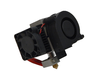
- Extruder
- Witbox extruder.
- Frame
- Official modified Prusa. It has a recess in the Y axis area to prevent friction may exist once the leveling of the base if the screw protrudes. File:Frame&base Hephestos.dxf.zip
- Volume Printing
- 215x210x180 mm
Printed pieces
Thingiverse page: http://www.thingiverse.com/thing:371842
Own desings
X Axis coupling chain stitch
Piece Downloads 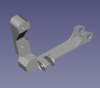
File:Acople cadeneta Eje X.zip

Mechanical Endstop clamping X axis
Piece Downloads
File:EjeX final de carrera.zip

Mechanical Endstop clamping Y axis
Pieces Downloads 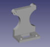
File:EjeY final carrera marco.zip 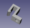
File:EjeY final carrera base.zip


Mechanical Endstop clamping Z axis
Piece Downloads 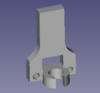
File:Eje Z final carrera.zip

Hot End security
Piece Downloads 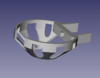
File:Seguridad Hot end.zip

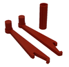
Tools
Piece Downloads 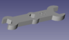
File:Llave fija impresa archivos.zip

LCD support
Piece Downloads 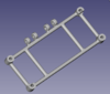
File:Soporte lcd.stl 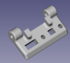
File:Bisagra lcd.stl


Fan support
Piece Downloads 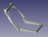
File:Soporte ventilador archivos.zip

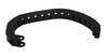
Filament holder


Modified
X Axis carriage
- The original carriage will have made the following changes:
- -Attach to rewind Igus chain stitch at the top (above the bearings).
- -Addition of a small cap to ensure contact with the limit of X axis (on the side, next to the linear bearing carriage below)
Original Modified X Axis carriage (Power CODE) X Axis carriage (Hephestos) 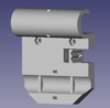
File:Eje X carro A archcivos.zip


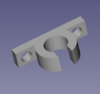
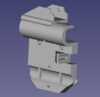
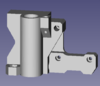
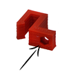
Clamping the left Z Axis motor
- -Incorporated hitch chainstitch.
Original Modified Clamping the left Z Axis motor (Power CODE) Clamping the left Z Axis motor (Hephestos) 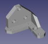
File:I3-zbottom izq.stl File:Eje Z soporte inferior izquierda archivos.zip


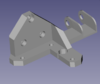
End of the X Axis motor
- To provide robustness to the screw to adjust the height in Z.
- -The base is elongated and has reduced the looseness of the nut to prevent the screw from moving.
- -Has shifted the screw hole out to get a better accuracy in mechanical Endstop activation.
Original Modified X Axis left (Power CODE) X Axis left (Hephestos) 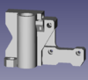
File:EjeX izquierda.zip
.PNG)
.PNG)
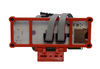
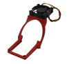
RAMPS support
- They have added three hooks. Each hook allows through a bridle, hold and collect all the cables connected to the RAMPS. By guiding the cables through the side and into the plate at the top left corner promotes cooling of drivers having no cables above the sinks.
Original Modified RAMPS support (Witbox) RAMPS support (Hephestos) 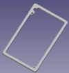
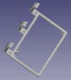
File:Suplemento RAMPS(original).stl File:Soporte RAMPS archivos.zip


Complete Kit
Complete Kit pieces to Hephestos:
Bill of Materials
Tools
Piece Name Quantity
Allen key s/long Ø 2 UNIOR Ø 2 mm 1 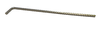
Allen key s/long Ø 2.5 mm 1 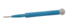
Ceramic screw driver trimmer for electronics. 1 
Precision Needle 0.4mm diameter 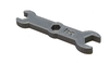
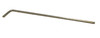
Printed spanner 10 (M6) - 13 (M8) - 17 (M10) 1

Electronic
Piece Name Quantity
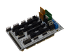
Ramps 1.4 1 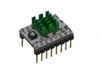
Stepstick Drivers A4988 4 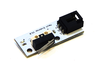
Endstop 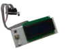
LCD control panel 1 
USB cable (type B), 1.8 m. 1 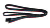
Motor wire Nema 17 4 
EndStop wire with click and female connector 40 cm 2 EndStop wire with click and female connector 85 cm 1 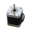
Motor Nema 17 4 
Wire kit extruder (Motor wire Nema (with connector) + Thermistor wire with connector + Fan and blower wire + Heater cartridge) 1 
150 mm of flexible wire of two bicolor threads by 1 mm² 1 
Power supply 220 AC 12 DC 100W 1 
Wire 220AC (European) 1 
Printed support for lcd 1 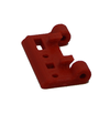
Printed support for lcd 1 
Printed support for ramps 1 
Printed support for fan 1 
M3x10 Screw - DIN-912 Class 8.8 Black 4 
M3x12 Screw - DIN-912 Class 8.8 Black 2 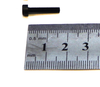
M3x16 Screw - DIN-912 Class 8.8 Black 2 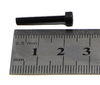
M3x20 Screw - DIN-912 Class 8.8 Black 4 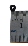
M3 Nut - DIN 934 Class 8 Black 12 
Heat shrink tube 2.5 x 500 mm 1 
Black bridle 100 x 2.5 mm 10 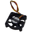
Brushless DC Cooling Fan - RD5010B12H with 20cm wire without connector 1 
Adapter/connector Jack-Ramps 1 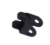
Plastic Drag Chain Link 15x35 mm 52


Extruder
Piece Name Quantity
Witbox Extruder ( direct extruder for 1.75 mm filament, with 0.4mm nozzle) 1 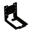
Extruder support 1 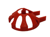
Hot End security 1 
M4 x 6mm Screw DIN-912 8.8 Class (with head for Allen 2.5mm) 2 M3x10 Screw - DIN-912 8.8 Class Black 2 M3 x16 Screw - DIN-912 8.8 Class Black 1 M3 Nut - DIN 934 Class 8 Black 1


X Axis
Piece Name Quantity
Chromed smooth rod 8mm x 370mm 2 M3x10 Screw - DIN-912 8.8 Class Black 4 M3x16 Screw - DIN-912 8.8 Class Black 2 M3x20 Screw - DIN-912 8.8 Class Black 2 
M3x25 Screw - DIN-912 8.8 Class Black 1 
M6x40 Screw - DIN-912 8.8 Class Black 1 M3 Nut - DIN 934 Class 8 Black 7 
M5 Nut - DIN 934 Class 8 Black 2 
M6 Nut - DIN 934 Class 8 Black 3 
X Axis Carriage A 1 
X Axis Carriage B 1 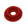
X Axis B623ZZ bearing Pulley 2 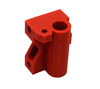
X Axis Right 1 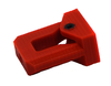
X Axis tensor B623ZZ bearing 1 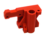
X Axis left 1 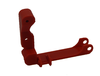
X Axis left thread chain coupling 1 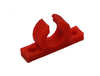
X Axis Endstop 1 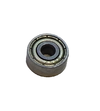
B623ZZ axial bearing 1 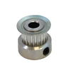
GT2 pulley (20 theet) 1 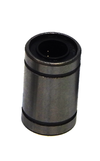
LM8UU Linear bearing 1 Black bridle 100x2.5mm 1


Y Axis
Piece Name Quantity
Chromed smooth rod 8mm x 340mm 2 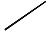
Black threaded rod M10x370mm 2 Black threaded rod M8 x 205mm 4 M3 x10 Screw - DIN-912 8.8 Class Black 7 M3 x16 Screw - DIN-912 8.8 Class Black 1 M3 x20 Screw - DIN-912 8.8 Class Black 1 M3 x25 Screw - DIN-912 8.8 Class Black 6 M3 Nut - DIN 934 Class 8 Black 7 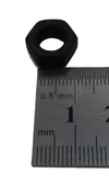
M8 Nut - DIN 934 Class 8 Black 22 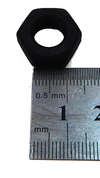
M10 Nut - DIN 934 Class 8 Black 12 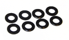
M8 Washer - DIN-125 Class 6 Black 22 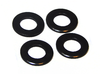
M10 Washer - DIN-125 Class 6 Black 12 Y Axis B623ZZ bearing Pulley 2 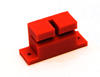
Y Axis belt holder 1 
Y Axis tensor B623ZZ bearing http://www.thingiverse.com/thing:68185 1 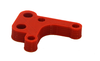
Y Axis motor 1 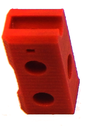
Y Axis Corner 1 
Y Axis base Endstop 1 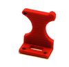
Y Axis frame Endstop 1 GT2 pulley (20 teeth) 1 LM8UU Linear bearing 3 Black bridle 100x2.5mm 11 
GT2 belt 6mmx1m 1 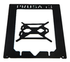
Aluminum base 1 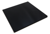
Methacrylate base 220x220x8mm holes 3.5mm 1 B623ZZ axial bearing 1 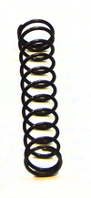
Spring (long: 30,5mm ; Outside diameter: 4,5mm; Wire thickness: 0.45mm) 4 
Glass 220x220x3mm 1 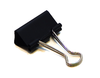
Black Biinder Clip (35x10mm) 4 Black bridle 100x2.5mm 11


.png)
Z Axis
Pieza Nombre Cantidad Chromed smooth rod 8mm x 320mm 2 Black threaded rod M5x300mm 2 M3x10 Screw - DIN-912 8.8 Class Black 16 
M3 x18 Screw - DIN-912 8.8 Class Black 2 M3 Nut - DIN 934 Class 8 Black 2 
Z Axis top support 1 
Z Axis right bottom support 1 
Z Axis Endstop 1 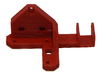
Z Axis left bottom support 1 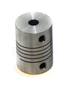
Flexible coupling aluminum 5 to 5 mm 2 Black aluminum frame 1


Assembly Guide
Required tools not included in the BOM
Piece Picture 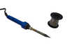
Welder and tin 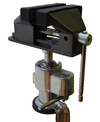
jaw 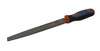
Metal lime 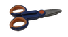
Scissors


Preparation before assembly
Prepare pulleys
- Materials Needed:
Piece Name Description Quantity LM8UU Linear bearing - 1 Polea Eje X y Eje Y rodamiento B623ZZ Pulley 2
- Assembly:

Step A

Step B

Step C

Step D
Preparation of the motors
- Materials Needed:
Piece Name Quantity Motor Nema 17 4 Metal lime 1 Jaw 1
- Assembly:

Step A

Step B

Step C
Embed nuts
- Materials Needed:
Picure Name 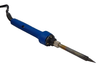
Welder Piece - Nut

- Assembly:

Step A

Step B

Step C

Step D

Step E

Step F
- Parts to be embed with nut:
Picture Detail Picture Name Nut Quantity 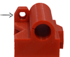
X Axis Right M5 Nut - DIN 934 Class 8 Black 1 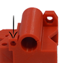
X Axis left M3 Nut - DIN 934 Class 8 Black 1 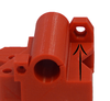
X Axis left M5 Nut - DIN 934 Class 8 Black 1 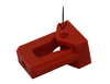
X Axis tensor B623ZZ bearing M3 Nut - DIN 934 Class 8 Black 1 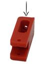
Y Axis tensor B623ZZ bearing M3 Nut - DIN 934 Class 8 Black 1 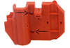
X Axis Carriage A M3 Nut - DIN 934 Class 8 Black 2 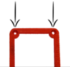
Fan support M3 Nut - DIN 934 Class 8 Black 2 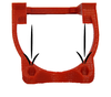
Fan support M3 Nut - DIN 934 Class 8 Black 2 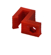
Y Axis base Endstop M3 Nut - DIN 934 Class 8 Black 1 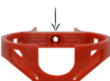
Hot End Security M3 Nut - DIN 934 Class 8 Black 1


Preparation of motor cables
- Materials Needed:
Picture Name Quantity Motor Nema 17 4 Motor Nema wire 17 4 Welder and tin 1 Heat shrink tube 2.5 x 500 mm 1
- Cable length (from base of engine to end of connector)
Motor Total length (cm) Motor length (cm) Extesnion lenght(cm) X 85 30 55 Y 50 20 30 Z Right 45 15 30 Z Left 65 30 35
- Note: Cut four pieces of heat shrink tubing Motor wire 2cm long.
- Note: Prepare motors X and Y axes before mounting the engines and Prusa Z Axis after mounting.
- Assembly:

Step A

Step B

Step C

Step D

Step E

Step F

Step G

Step H

Step I

Step J
- Note: Before welding cables Z axis motors, pass the bare wire through the motor hole.
- Assembly:

Step A

Step B
Power supply cable preparation
- Materials Needed:
Picture Name Quantity Scissors 1 Adapter/connector Jack-Ramps 1 Power supply 220 AC 12 DC 100W 1 150 mm of flexible wire of two bicolor threads by 1 mm² 1
- Assembly:

Step A

Step B

Step C

Step D

Step E
Step F

Step G
Axis assembly
X Axis
Enter bearings
- Materials Needed:
Piece Name Description Quantity LM8UU Linear bearing - 4 X Axis left Part of the left end of the X axis where will subject the said axis Nema 17 motor. 1 X Axis Right Part of the right end of the x axis is attached where the belt tensioner to said axis. 1
- Assembly:

Step A

Step B

Step C
Prepare the tensor X Axis
- Materials Needed:
Piece Name Description Quantity X Axis tensor B623ZZ bearing X Axis belt tensioner where is housed together with the pulley axial ball bearing B623ZZ 1 
Pulley Pulley mounted on the previous preparation 1 M3x20 Screw - DIN-912 8.8 Class Black 1 M6x40 Screw - DIN-912 8.8 Class Black 1
- Assembly:

Step A

Step B

Step C

Step D
Enter the X Axis tensor
- Materials Needed:
Piece Name Quantity 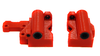
Assembly step 1 1 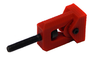
Assembly step 2 1 M6 Nut - DIN 934 Class 8 Black 3
- The objective of the tensor is load or unload a belt comfortably once set.
- Note: It is necessary to sand the pieces. The tensioner should slide perfectly with the piece that holds it.
- Assembly:

Step A

Step B

Step C
- Note: The two nuts are to be tightened in the end together. To do this with the aid of a nut wrench against the other, in this way it is achieved that these nuts are integral with the screw tightened. Now introducing the wrench as shown in the picture, a crank to slide linearly tensor is achieved.

Step D

Step E

Step F
- Note: With the help of the key nut and tighten nut to get a wing nut on the screw.
Introduce smooth rod bearings
- Materials Needed:
Piece Name Quantity Chromed smooth rod Ø 8mm x 370mm 2 LM8UU Linear bearing 3
- Assembly:
Step A
Step B
Prepare the X Axis Endstop sensor
- Materials Needed:
Piece Name Quantity X Axis Endstop 1 Endstop 1 M3 Nut - DIN 934 Class 8 Black 2 M3x10 Screw - DIN-912 8.8 Class Black 2
- Assembly:

Step A

Step B
Introduce the X Axis Endstop sensor in the smooth rod
- Materials Needed:
Piece Name Quantity 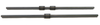
Assembly step 4 1 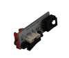
Assembly step 5 1
- Assembly:
Step A

Step B
Introduce the smooth rod in the side parts
- Materials Needed:
Piece Name Quantity Assembly step 1 1 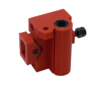
Assembly step 3 1 Assembly step 6 2
- Assembly:
- The length of the rod once joined in the side pieces, should be approximately 31 cm.
Step A
Step B
Mount the X Axis motor
- Materials Needed:
Piece Name Quantity Motor Nema 17 1 M3x10 Screw - DIN-912 8.8 Class Black 2 M3x16 Screw - DIN-912 8.8 Class Black 2 
Assembly step 7 1 X Axis left thread chain coupling 1
- Assembly:
- Note: Orient the motor cable from the top.

Step A

Step B

Step C
Introduce the adjustment screw for the X Axis Endstop
- Materials Needed:
Piece Name Quantity 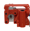
Assembly step 8 8 M3x25 Screw - DIN-912 8.8 Class Black 1
- Assembly:

Step A

Step B
Introduce the pulley on the X Axis motor
- Materials Needed:
Piece Name Quantity Motor Nema 17 1 GT2 pulley (20 theet) 1
- Assembly:
- Note: Use the 2mm Allen wrench to tighten the pulley to the motor axis by the chamfered area.

Step A

Step B

Step C
Z Axis
Couple the motor hold on the frame
- Materials Needed:
Piece Name Quantity Z Axis right bottom support 1 Z Axis left bottom support 1 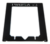
Black aluminum frame 1 M3x10 Screw - DIN-912 8.8 Class Black 6

- Assembly:

Step A

Step B
Couple the Z motors
- Materials Needed:
Piece Name Quantity Motor Nema 17 2 
Assembly step 1 1 M3x10 Screw - DIN-912 8.8 Class Black 6
- Assembly:
Note: Orient the motor cable to the frame

Step A
Step B
Attach the top tether of smooth rods
- Materials Needed:
Piece Name Quantity Black aluminum frame 1 Z Axis top support 2 M3x10 Screw - DIN-912 8.8 Class Black 2 M3x18 Screw - DIN-912 8.8 Class Black 2
- Assembly:
Note: It is necessary to sand the pieces.
Step A
Step B
Prepare the Z Axis Endstop
- Materials Needed:
Piece Name Quantity Endstop 1 Z Axis Endstop 1 M3x10 Screw - DIN-912 8.8 Class Black 2 M3 Nut - DIN 934 Class 8 Black 2
- Assembly:

Step A

Step B

Step C
Union X Axis with Z Axis: Insert threaded rods
- Materials Needed:
Piece Name Quantity 
X Axis 1 
Z Axis Endstop 1

- Assembly:

Step A

Step B
Union X Axis with Z Axis: Introduce smooth rod
- Materials Needed:
Piece Name Quantity 

Assembly step 2 and 3 1 
Chromed smooth rod 8mm x 320mm 2

- Assembly:

Step A

Step B
Union X Axis with Z Axis: Union with X Axis:
- Materials Needed:
Piece Name Quantity 
Assembly step 6 1 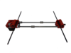
Assembly step 5 1
- Assembly:

Step A

Step B

Step C
Union X Axis with Z Axis: Flexible coupling
- Materials Needed:
Piece Name Quantity 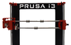
Assembly step 7 1 Flexible coupling aluminum 5 to 5 mm 2
- Assembly:
Step A
Step B

Step C

Step D
Union X Axis with Z Axis: Z Axis Endstop
- Materials Needed:
Piece Name Quantity Assembly step 8 1 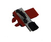
Assembly step 4 1
- Assembly:
- Note: Paste with adhesive for plastics the step assembly 4 to the motor bracket.

Step A

Step B
Y Axis
Preparation of M10 threaded rod
- Materials Needed:
Piece Name Quantity Black threaded rod M10x370mm 2 M10 Nut - DIN 934 Class 8 Black 4 M10 Washer - DIN-125 Class 6 Black 4 [[File:|100px|]] M10 Washer -(Ø 30 mm) DIN-9021 Negra 4 [[File:|100px|]] M10 Nut - DIN 934 Class 8 Black 4
- Assembly:
Step A
Step B
Preparation of smooth rods
- Materials Needed:
Piece Name Quantity Chromed smooth rod Ø 8mm x 340mm 2 LM8UU Linear bearing 3
- Assembly:
Step A
Step B
Union of smooth rods with threaded rods
- Materials Needed:
Piece Name Quantity Y Axis Corner 4 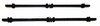
Assembly step 1 1 
Assembly step 2 1
- Assembly:
Step A
Step B
Secure with nuts
- Materials Needed:
Piece Name Quantity M10 Nut - DIN 934 Class 8 Black 4 M10 Washer - DIN-125 Class 6 Black 4
- Assembly:
Step A
Step B

Step C
Secure with flnages
- Materials Needed:
Piece Name Quantity 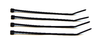
Black bridle 100x2.5mm 4
- Assembly:

Step A

Step B

Step C
Preparation of Y Axis tensioner
- Materials Needed:
Piece Name Quantity Pulley 1 Y Axis tensor B623ZZ bearing 1 M3 x20 Screw - DIN-912 8.8 Class Black 1 M3 x25 Screw - DIN-912 8.8 Class Black 1 M3 Nut - DIN 934 Class 8 Black 2
- Assembly:
Note: The 25 mm screw is used as shaft for the pulley and the 20mm screw for the tensioner.

Step A

Step B
Preparation of Y Axis motor
- Materials Needed:
Piece Name Quantity Motor Nema 17 1 Y Axis motor 1 M3 x10 Screw - DIN-912 8.8 Class Black 3
- Assembly:

Step A

Step B
Preparation of the threaded rods M8 - Part 1
- Materials Needed:
Piece Name Quantity Varilla roscada negra M8 x 205mm 4 M8 Washer - DIN-125 Class 6 Black 6 M8 Nut - DIN 934 Class 8 Black 6 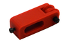
Assembly step 6 1 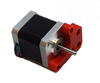
Assembly step 7 1
- Assembly:

Step A

Step B
Preparation M8 threaded rod - Part 2
- Materials Needed:
Piece Name Quantity M8 Washer - DIN-125 Class 6 Black 8 M8 Nut - DIN 934 Class 8 Black 8 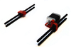
Assembly step 8 1
- Assembly:

Step A

Step B
Union of the rods
- Materials Needed:
Piece Name Quantity 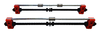
Assembly step 5 1 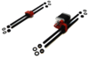
Assembly step 9 1
- Assembly:

Step A

Step B
Secure with nuts the structure
- Materials Needed:
Piece Name Quantity M8 Nut - DIN 934 Class 8 Black 8 M8 Washer - DIN-125 Class 6 Black 8 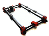
Assembly step 10 1
- Assembly:

Step A

Step B

Step B
Preparation of the aluminum base
- Materials Needed:
Piece Name Quantity 
Aluminum base 1 Y Axis belt holder 1 M3 x10 Screw - DIN-912 8.8 Class Black 2

- Assembly:

Step A

Step B
Secure the base aluminum with flanges
- Materials Needed:
Piece Name Quantity 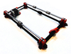
Assembly step 11 1 
Assembly step 12 1 Black bridle 100x2.5mm 3
- Assembly:

Step A

Step B

Step C

Step D

Step E

Step F

Step G

Step H
Prepare the Endstop of the base
- Materials Needed:
Piece Name Quantity Y Axis Endstop 1 M3 x25 Screw - DIN-912 8.8 Class Black 1
- Assembly:

Step A

Step B
Secure the Endstop at the base
- Materials Needed:
Piece Name Quantity 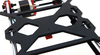
Assembly step 13 1 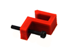
Assembly step 14 1
- Assembly:

Step A

Step B

Step C

Step D
Place the belt of the Axis Y
- Materials Needed:
Piece Name Quantity GT2 belt 6mmx1m 1 GT2 pulley (20 theet) 1 Black bridle 100 x 2.5 mm 4
- Assembly:
- Note: Turn the set
- Note: Tighten pulley with 2mm Allen wrench

Step A

Step B

Step C

Step D
- Note: Screw out screw to slacken the tensioner

Step E

Step F

Step G

Step H

Step I

Step J

Step K

Step L
- Note: Align belt

Step M

Step N

Step Ñ

Step O
- Note: Tighten the belt tensioner bolt tightening
Tighten all nuts
- Materials Needed:
Piece Name Quantity Printed spanner 10 (M6) - 13 (M8) - 17 (M10) 1
- Assembly:
- Note: It is necessary to file the burrs.

Step A
Place the methacrylate base
- Materials Needed:
Piece Name Quantity Methacrylate base 220x220x8mm holes 3.5mm 1 M3 x25 Screw - DIN-912 8.8 Class Black 4 Spring (long: 30,5mm ; Outside diameter: 4,5mm; Wire thickness: 0.45mm) 4
- Assembly:
- Note: It is necessary to file the burrs.

Step A

Step B
Prepare the Y Axis Endstop on the frame
- Materials Needed:
Piece Name Quantity Y Axis Endstop 1 Endstop 1 M3x10 Screw - DIN-912 8.8 Class Black 2 M3 Nut - DIN 934 Class 8 Black 2
- Assembly:

Step A

Step B
Secure the Y Axis Endstop on the frame
- Materials Needed:
Piece Name Quantity 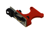
Assembly step 19 1 Black aluminum frame 1 M3x16 Screw - DIN-912 Class 8.8 Black 1 M3 Nut - DIN 934 Class 8 Black 1
- Assembly:

Step A

Step B

Step C

Step D
Step E
Union Y Axis with the X and Z axes: Snap axes
- Materials Needed:
Piece Name Quantity 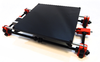
Y Axis 1 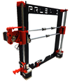
XZ Axis 1

- Assembly:

Step A

Step B

Step C
Union Y Axis with the X and Z axes: Fit and tighten nuts
- Materials Needed:
Piece Name Quantity 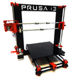
Assembly step21 1 Printed spanner 10 (M6) - 13 (M8) - 17 (M10) 1
- Assembly:

Step A
Extruder
Prepare the carriage
- Materials Needed:
Piece Name Quantity X Axis Carriage A 1 X Axis Carriage B 1 M3x20 Screw - DIN-912 8.8 Class Black 1 M3 Nut - DIN 934 Class 8 Black 1
- Assembly:

Step A

Step B
Place the carriage in the X axis
- Materials Needed:
Piece Name Quantity 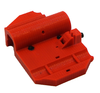
Step assembly 1 1 Prusa 1
- Assembly:

Step A

Step B

Step C

Step D
Secure the carriage with a flange
- Materials Needed:
Piece Name Quantity 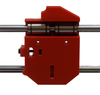
Step assembly 2 1 Black bridle 100 x 2.5 mm 1
- Assembly:

Step A

Step B

Step C

Step D

Step E
Place the belt on the X Axis
- Materials Needed:
Piece Name Quantity GT2 belt 6mmx1m 1 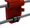
Step assembly 3 1 Black bridle 100 x 2.5 mm 4
- Assembly:

Step A

Step B

Step C

Step D

Step E

Step F
Screw the Extruder support
- Materials Needed:
Piece Name Quantity Extruder support 1 M3x10 Screw - DIN-912 8.8 Class Black 2
- Assembly:

Step A

Step B
Montar el Extrusor
- Materials Needed:
Piece Name Quantity Witbox Extruder 1 M4 x 6mm Screw DIN-912 8.8 Class (with head for Allen 2.5mm) 2
- Assembly:
- Note: This step is necessary to remove the nozzle of the extruder.
- Nota: Secure with screws the Extruder.

Step A

Step B

Step C
Placing the blower nozzle and Hot end security
- Materials Needed:
Piece Name Quantity M3 x20 Screw - DIN-912 8.8 Class Black 1 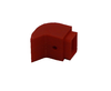
Blower nozzle of the Witbox extruder 1 Hot End security 1

- Assembly:
- Nota: The Hot end security is a opcional complement and no necessary for the correct printer working, but its use is highly recommended to avoid burns.

Step A

Step B

Step C
Place the glass on the base
- Materials Needed:
Piece Name Quantity Glass 220x220x3mm 1 Black Biinder Clip (35x10mm) 4
- Assembly:

Step A

Step B

Step C
Electronic
Place the RAMPS 1.4
- Materials Needed:
Piece Name Quantity
Ramps 1.4 1 M3x20 Tornillo - DIN-912 Clase 8.8 Negro 2 Soporte Ramps 1
- Montaje:

Step A

Step B

Step C
Preparar el panel de control LCD
- Materials Needed:
Piece Name Quantity
Panel de Control LCD 1 Soporte LCD 2 Bisagra LCD 1 M3x10 Tornillo - DIN-912 Clase 8.8 Negro 4 M3 x20 Tornillo - DIN-912 Clase 8.8 Negro 2
- Montaje:

Step A

Step B

Step C

Step D
Montar el panel de control LCD en el marco
- Materials Needed:
Piece Name Quantity
Conjunto del paso 2 1 M3 Tuerca - DIN 934 Clase 8 Negro 2
- Montaje:

Step A

Step B

Step C
Meter los cables en la cadenenta del Eje X
- Materials Needed:
Piece Name Quantity
Cadeneta 25 eslabones 1 Cadeneta 27 eslabones 1 Kit cables para extrusor (Cable motor Nema (con conector) + Cable termistor extrusor con conector + Cable para ventilador y blower + Cable cartucho calefactor) 1

- Montaje:
- Nota: Para facilitar la tarea mete los cables uno a uno.

Step A

Step B

Step C

Step D
Colocar la cadeneta del Eje X
- Materials Needed:
Piece Name Quantity

Cadeneta Eje X con cables 1
- Montaje:
- Nota: La cadeneta de 25 eslabones une el carro del Eje X con el extremo del Eje X Izquierdo.
Step A

Step B

Step C

Step D

Step E

Step F
Meter los cables del Eje Z y colocar la cadeneta del Eje Z
- Materials Needed:
Piece Name Quantity 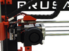
Conjunto del paso 5 1 Cable final de carrera 85 cm 1
- Montaje:
- Nota: Introducir por la cadeneta del Eje Z los cables del motor y del sensor final de carrera del Eje X.

Step A

Step B
- Nota: La cadeneta de 27 eslabones une el extremo del Eje X Izquierdo con la pieza del Eje Z inferior izquierda.

Step C

Step D

Step E
Preparar el ventilador
- Materials Needed:
Piece Name Quantity
Ventilador 50 x 50 mm 1 Soporte ventilador 1 M3 x16 Tornillo - DIN-912 Clase 8.8 Negro 2
- Montaje:

Step A

Step B
Conexionado y guiado de los cables
Diagrama de conexionado de cables

- Materials Needed:
Piece Name Quantity
Brida negra 100x2.5mm 11 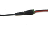
Cable fuente de alimentación preparado 1 Cable final de carrera 40 cm 2
Conexionado del extrusor

Step A

Step B

Step C
- Nota: Sujetar con una brida los cables del extrusor

Step D

Step E
Guiado de los cables de los motores
- Nota: Sujetar con bridas los cables de los motores

Step A

Step B
Guiado de los cables de final de carrera

Step A

Step B

Step C
Guiado y conexionado de los cables en la placa
- Nota: Sujeta los cables con bridas, y conecta éstos a la placa

Step A

Step B

Step C
- Nota: Guía los cables por la pieza impresa que sujeta a la RAMPS y asegúralos con las bridas
- Nota: Conecta en la clema de la placa los cables de los ventiladores y la fuente de alimentación.

Step D

Step E

Step F
Colocar el ventilador
- Materials Needed:
Piece Name Quantity
Conjunto del paso 8 1 M3 x12 Tornillo - DIN-912 Clase 8.8 Negro 2
- Assembly:
- Nota: Desconecta el panel de control LCD de la Ramps antes de colocar el ventilador y pasalo por el hueco de la pieza.

Step A

Step B

Step C
Colocación del soporte para la bobina de filamento
- Materials Needed:
Piece Name Quantity
Soporte rollos de filamento 1

- Assembly:
- Nota: Desconecta el panel de control LCD de la Ramps antes de colocar el ventilador y pasalo por el hueco de la pieza.

Step A

Step B

Step C