Design nearly done - construction started...
Posted by Maxx Mayhem
|
Re: Design nearly done - construction started... March 26, 2014 03:30PM |
Registered: 11 years ago Posts: 256 |
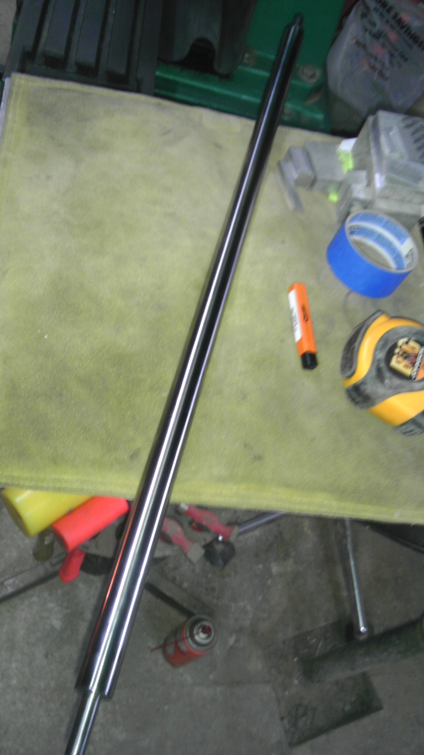
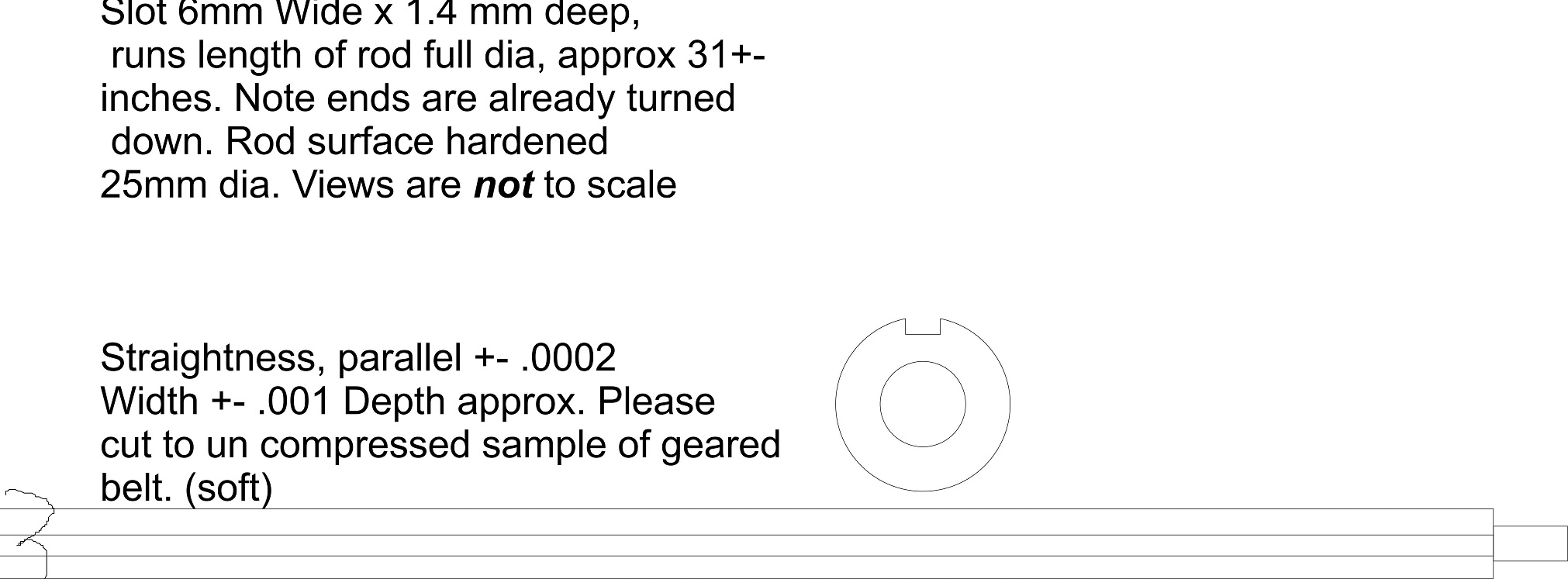
So basically, I have this, and a 12 mm rod which will be slotted to make a rack and pinion drive for the x, y axis'. From what I have read in some tech data online, the benefit to post hardening milling is that it tends not to warp, once you cut a slot in a round and harden it, it will usually deform. I had come up with a way to slip this part across my mill way, using just a piece of angle, the problem is, my mill is nowhere near firm enough to do hardened work. You must use carbide, more than 1 end mill will be needed. The only end mills I have found that are 6mm x 3/8" are Enco, which has only hss and cobalt. I would need to buy a collet, 1/2 dozen end mills, clamping stuff, and I'm still fighting a mill really meant for mild steels and aluminum. So I think I will wind up farming this out. Kind of like with things like silicon heat mats, and hot ends, there are experts out there, and every once in a while, it ends up best letting them do what they're best at..
|
Re: Design nearly done - construction started... March 26, 2014 03:59PM |
Registered: 10 years ago Posts: 1,381 |
If a rubber belt is going to be located in the slot, do you really need 0.0002" tolerance.
Consider reviewing the mfg tolerance of the belt pitch/thickness, and run a test indicator over the belt to verify, maybe you can open up the tolerance a little.
Tks for sharing, looking forward to learning how it works out.
Consider reviewing the mfg tolerance of the belt pitch/thickness, and run a test indicator over the belt to verify, maybe you can open up the tolerance a little.
Tks for sharing, looking forward to learning how it works out.
|
Re: Design nearly done - construction started... March 26, 2014 04:04PM |
Registered: 10 years ago Posts: 474 |
Maxx I know you've made a decision to go with this kind of drive but I don't think you going to be happy with it. If you have pulleys and belts make a little test piece out of wood cut a slot glue a small piece of belt in. Make another piece out of wood in which a pulley can be mounted and locked so it does not rotate. Put one on top of the other and push back and forth to test the backlash. Belts are meant to be bent around a pully if you think of it the rubber is what compresses and the fiber or the steel in the belt is what stays the same the fiber is located in the center of the backing so when belt is bent teeth come closer together this is what makes it fit the radius of the pully belt in a flat position does not fit the pulleys very well.
|
Re: Design nearly done - construction started... March 26, 2014 04:22PM |
Registered: 11 years ago Posts: 256 |
Well, CNCD, you've given me another idea, something that you had showed me about a month ago, with a looped belt and then I'd use a pair of idlers at either side of the pulley. Then I'd just need to get some open lmm25s and do it that way, because I'm seeing the issue with the contact. It would seem that it will run my way, but it would take a lot more torque wrapping the belt. Then, I could use toothed lands to stabilize the belt in the linear direction and save at least a couple of hundred bucks!  I would have abut 270 deg of constant contact, but still not be flapping a 7' belt. The more I think about this , the better it starts to sound.
I would have abut 270 deg of constant contact, but still not be flapping a 7' belt. The more I think about this , the better it starts to sound.
|
Re: Design nearly done - construction started... March 26, 2014 05:20PM |
Registered: 10 years ago Posts: 474 |
|
Re: Design nearly done - construction started... March 26, 2014 06:23PM |
Registered: 11 years ago Posts: 256 |
|
Re: Design nearly done - construction started... March 26, 2014 07:27PM |
Registered: 10 years ago Posts: 474 |
Since forces are going back and forth I wouldn't use a spring system. Motor shafts even the small ones on Nema 17 can take quite a bit if I remember right there is no problem running 20 pounds pull force on the belt even on a Nema 17 and if you built the system with plates and bearings on both sides of the pully it would be as much as the belt could handle hundreds of pounds. I would at make some kind a clamp for one side of the belt and make it adjustable on one side of the machine to pull the belt and clamp it stationary to the machine on the other side
Edited 1 time(s). Last edit at 03/26/2014 07:29PM by cnc dick.
Edited 1 time(s). Last edit at 03/26/2014 07:29PM by cnc dick.
|
Re: Design nearly done - construction started... March 26, 2014 10:59PM |
Registered: 10 years ago Posts: 10 |
Incredible build, you sure have put a lot of time into it....I applaud you  . What you might be able to do on your belt tensioners is something I am working on. It is a WIP so I can't verify yet its effectiveness....but, it is the same principal used by the cam chain tensioner on many motorcycles.
Like many belts used by reprappers, a cam chain depends on teeth engagement, not high tension to create enough friction forces(like a v-belt), to keep from slipping. Of course, a cam chain does operate at high tension but that is due too high forces generated in the valve train, since moving a "print head" around generates much smaller forces this should be easily adaptable to a tensioning system for repraps.
Use a torsion spring to turn a screw with a very low pitch...end of screw(linear motion) pushes against tensioner. With proper "ramp" on your screw, the torsion spring will turn it to tension belt but any force pushing against the tensioner will NOT cause the screw to turn and back out. If system generates slack, the torsion spring turns screw a little more and removes slack. An automatic anti-backlash belt tensioner!
I've already started assembling my build for testing and the tensioning assembly is the last component in my belt path I have to complete. Hope to post pictures of my build soon, will provide link here when I do if anyone is interested.
Edited 1 time(s). Last edit at 03/27/2014 11:22AM by Creo.
. What you might be able to do on your belt tensioners is something I am working on. It is a WIP so I can't verify yet its effectiveness....but, it is the same principal used by the cam chain tensioner on many motorcycles. Like many belts used by reprappers, a cam chain depends on teeth engagement, not high tension to create enough friction forces(like a v-belt), to keep from slipping. Of course, a cam chain does operate at high tension but that is due too high forces generated in the valve train, since moving a "print head" around generates much smaller forces this should be easily adaptable to a tensioning system for repraps.
Use a torsion spring to turn a screw with a very low pitch...end of screw(linear motion) pushes against tensioner. With proper "ramp" on your screw, the torsion spring will turn it to tension belt but any force pushing against the tensioner will NOT cause the screw to turn and back out. If system generates slack, the torsion spring turns screw a little more and removes slack. An automatic anti-backlash belt tensioner!
I've already started assembling my build for testing and the tensioning assembly is the last component in my belt path I have to complete. Hope to post pictures of my build soon, will provide link here when I do if anyone is interested.
Edited 1 time(s). Last edit at 03/27/2014 11:22AM by Creo.
|
Re: Design nearly done - construction started... March 27, 2014 12:33AM |
Registered: 10 years ago Posts: 474 |
|
Re: Design nearly done - construction started... March 27, 2014 11:24AM |
Registered: 10 years ago Posts: 10 |
Changing directions wont affect the setup I described and that is the whole reason for my attempting to adapt it to repraps. A compression spring pushing a bolt linearly would be affected, but a torsion spring turning the scew will not. Picture a leadscrew, like you'll find on your machining equipment, screwed into a stationary nut and unconstrained at both ends.....now apply a pure axial compression load on one end of the leadscrew...the leadscrew is not going to want to turn from just an axial force. There is no way a reprap is going to produce enough tension in a belt to back out a screw with proper mechanical advantage(determined by angle of inclined plane creating the threads).
Spark ignition engines can experience moments of reverse rotation when shut off or when a start sequence fails to get engine running...if you've ever experienced kick back when trying to kick-start a large bore single cylinder 4 stroke motorcycle you KNOW this is true.
I did not invent this design, simply attempting to adapt it over to repraps from a proven implementation.
Maybe there is something else I am overlooking....I will find out as soon as I mount and test my tensioners.
|
Re: Design nearly done - construction started... March 27, 2014 12:36PM |
Registered: 11 years ago Posts: 256 |
My idea is to have some sort of symmetrically sprung pair of tensioners to hold the belt in a 270 deg contact with the gear. After doing a couple of tests yesterday, I started thinking about fit vs. wear, and late fit (after wear) and came to the conclusion that CNCD, you are correct, I'd ultimately find a reliability issue with my previous design. The differences in hardness between thew belt and gear are significant. The gear would have had to be machined down to (a flat of) around 4 mm, engaging just a couple of teeth at a time. So I am now reasonably sure that the wear characteristics would prove to be unacceptable. So the tensioners would be proper sized bearings on a floating unit with tension springs top and bottom, and some sort of yet to be designed dampener. Note the belt is not drawn, because, well, I just got up and drawing the belt would be a PITA, but I think you can visualize its path.
|
Re: Design nearly done - construction started... April 05, 2014 12:03PM |
Registered: 11 years ago Posts: 256 |
I ran into a possible issue with the length of the linear rods, concerning the possibility of flexing and drooping. Fortunately, the frame of my machine is constructed heavy enough to allow a stressed configuration, with the rods on the long axis bolted to the endcaps and held in tension. This will prevent any tendency for the 12mm rod not to hold its linearity. The main, 25 mm rod is of less concern, though it is also bolted in to prevent it rotating. A note about the rods... I got most of my rods from VXB and they are fine, however there are no engineering specs available. The 25 mm rod came from Misumi, and they have full engineering specs on the website. Further, they will cut to length to the mm, and sell you only what you need. It is more complicated to place the order from Misumi, but there are definite advantages...
Things are going to start coming together now, I do have a couple of critical parts still on order, but construction is nearing the home stretch.
Things are going to start coming together now, I do have a couple of critical parts still on order, but construction is nearing the home stretch.
|
Re: Design nearly done - construction started... April 06, 2014 06:19PM |
Registered: 11 years ago Posts: 256 |
|
Re: Design nearly done - construction started... April 09, 2014 05:51PM |
Registered: 11 years ago Posts: 256 |
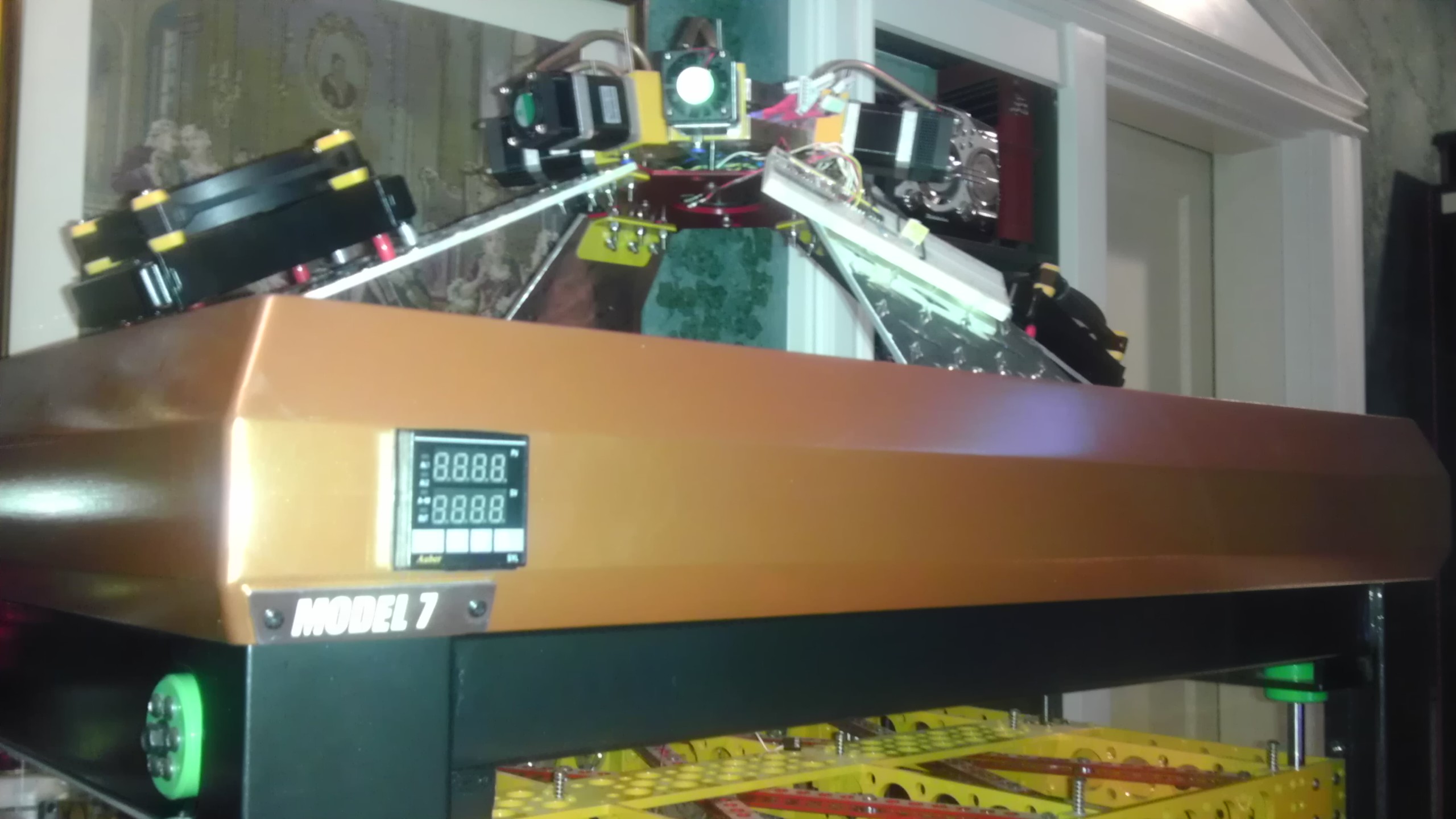
The heater arrived today from MEI. It was made to my specs, for a pretty reasonable price. Next I'll need to get the glass and the silicone foam insulation, I will use RTV for assembly. This heater has a thermocouple that will be used for control, via an Auber Instruments PID, and a solid state relay. I will glue in a thermistor to report temps to the Ramps board. The controller is fully programmable, so all of the heater control operations, and all amperage is totally separate from ramps, I do believe this will eliminate a host of problems. This heater runs on mains current, once you get to this size, I think it is the most practical way to do it.
MEI specializes in short runs and one offs, so to anybody who is looking to do an odd or large size, and one of the 3D vendors does not have what you need, this might be a good option. (just google them) I got mine in just over a month, and it appears to be well made. The glasses are there for scale.
arrived today from MEI. It was made to my specs, for a pretty reasonable price. Next I'll need to get the glass and the silicone foam insulation, I will use RTV for assembly. This heater has a thermocouple that will be used for control, via an Auber Instruments PID, and a solid state relay. I will glue in a thermistor to report temps to the Ramps board. The controller is fully programmable, so all of the heater control operations, and all amperage is totally separate from ramps, I do believe this will eliminate a host of problems. This heater runs on mains current, once you get to this size, I think it is the most practical way to do it. MEI specializes in short runs and one offs, so to anybody who is looking to do an odd or large size, and one of the 3D vendors does not have what you need, this might be a good option. (just google them) I got mine in just over a month, and it appears to be well made. The glasses are there for scale.
|
Re: Design nearly done - construction started... May 15, 2014 07:19PM |
Registered: 10 years ago Posts: 474 |
|
Re: Design nearly done - construction started... May 16, 2014 08:02PM |
Registered: 11 years ago Posts: 256 |
Hi all, I've been doing customer work for the past several weeks, but I am going to try and finish up a couple of items in the next couple of weeks... Mount the cold end assy. and liquid cooling system on the top of the printer; finish fabrication on the power supply covers, get some tempered glass and laminate up the bed, and finish design on the filament rack. This will leave only the (most important part) carriage / hot end and final assembly. There will still be a bunch of electronics but at that point I can finally start testing. The longer this build goes, the more things I come up with to add to this machine. So it is kind of a double edged sword, balanced between it getting done sooner and ending up cooler. But that is all part of my open ended process...
|
Re: Design nearly done - construction started... May 25, 2014 04:32PM |
Registered: 11 years ago Posts: 256 |
I managed to get a few days over the holiday weekend (thanks to my wood supplier whose ability to take an order is, not shockingly, absent) anyway, I got the upper assembly, brackets, cooling components and FINALLY cold end mounted....
|
Re: Design nearly done - construction started... May 27, 2014 07:39PM |
Registered: 11 years ago Posts: 256 |
|
Re: Design nearly done - construction started... June 29, 2014 08:13AM |
Registered: 10 years ago Posts: 474 |
|
Re: Design nearly done - construction started... June 30, 2014 09:29AM |
Registered: 10 years ago Posts: 474 |
Max I don't know who this guy is but a looks like he just copied and pasted one of my replies I made to you just seems a little weirdQuote
nhathaitrieu6
Maxx you are not that transparent it's just that there's only a few ways to achieve what you want to do. And me being a mechanical type like you obviously I think of the problem and then tried to solve it. If two people think the same way attacking a problem usually come out close to the the same solution
|
Re: Design nearly done - construction started... July 06, 2014 08:36AM |
Registered: 10 years ago Posts: 474 |
|
Re: Design nearly done - construction started... February 07, 2015 07:34PM |
Registered: 10 years ago Posts: 4 |

Sorry, only registered users may post in this forum.